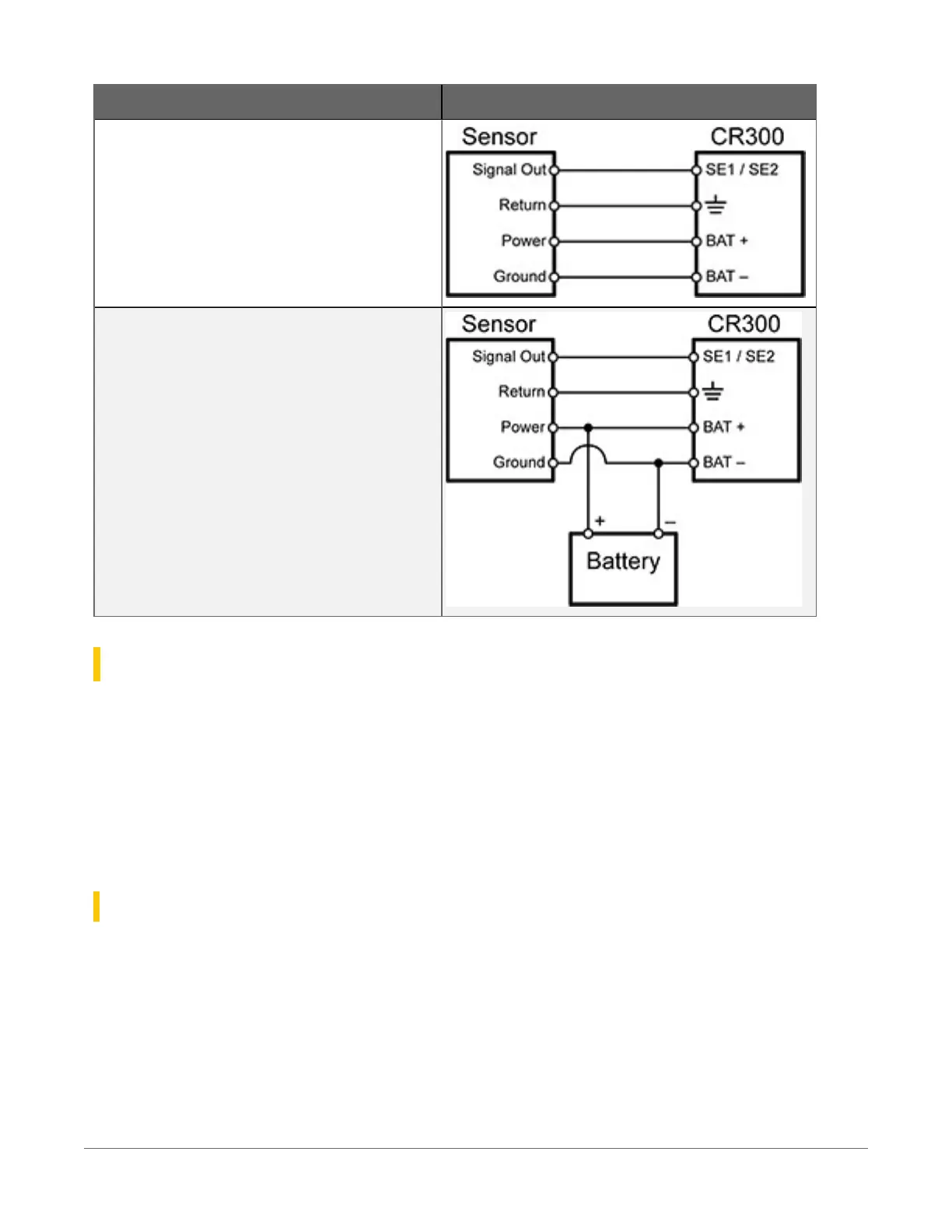
Sensor type Connection example
4-wire transmitter using data logger power
4-wire transmitter using external power
18.3 Resistance measurements
Bridge resistance is determined by measuring the difference between a known voltage applied to
the excitation (input) of a resistor bridge and the voltage measured on the output arm. The data
logger supplies a precise voltage excitation via VX terminals. Return voltage is measured on
analog input terminals configured for single-ended (SE) or differential (DIFF) input. The result of
the measurement is a ratio of measured voltages.
See also Resistance measurement specifications(p. 245).
18.3.1 Resistance measurements with voltage excitation
CRBasic instructions for measuring resistance with voltage excitation include:
l
BrHalf() - half bridge
l
BrHalf3W() - three-wire half bridge
l
BrHalf4W() - four-wire half bridge
18. Measurements95