o
-CELL215 average = 75 mA
o
-CELL220 average = 75 mA
o
-CELL225 average = 75 mA
Wi-Fi Additional Current Contribution at 12 VDC:
l
Client mode communicating: 70 mA typical
l
Client mode idle: 7 mA typical
l
Access point mode communicating: 70 mA
l
Access point mode idle: 62 mA typical
l
Idle (use IPNetPower() or DevConfig setting to disable): <0.1 mA
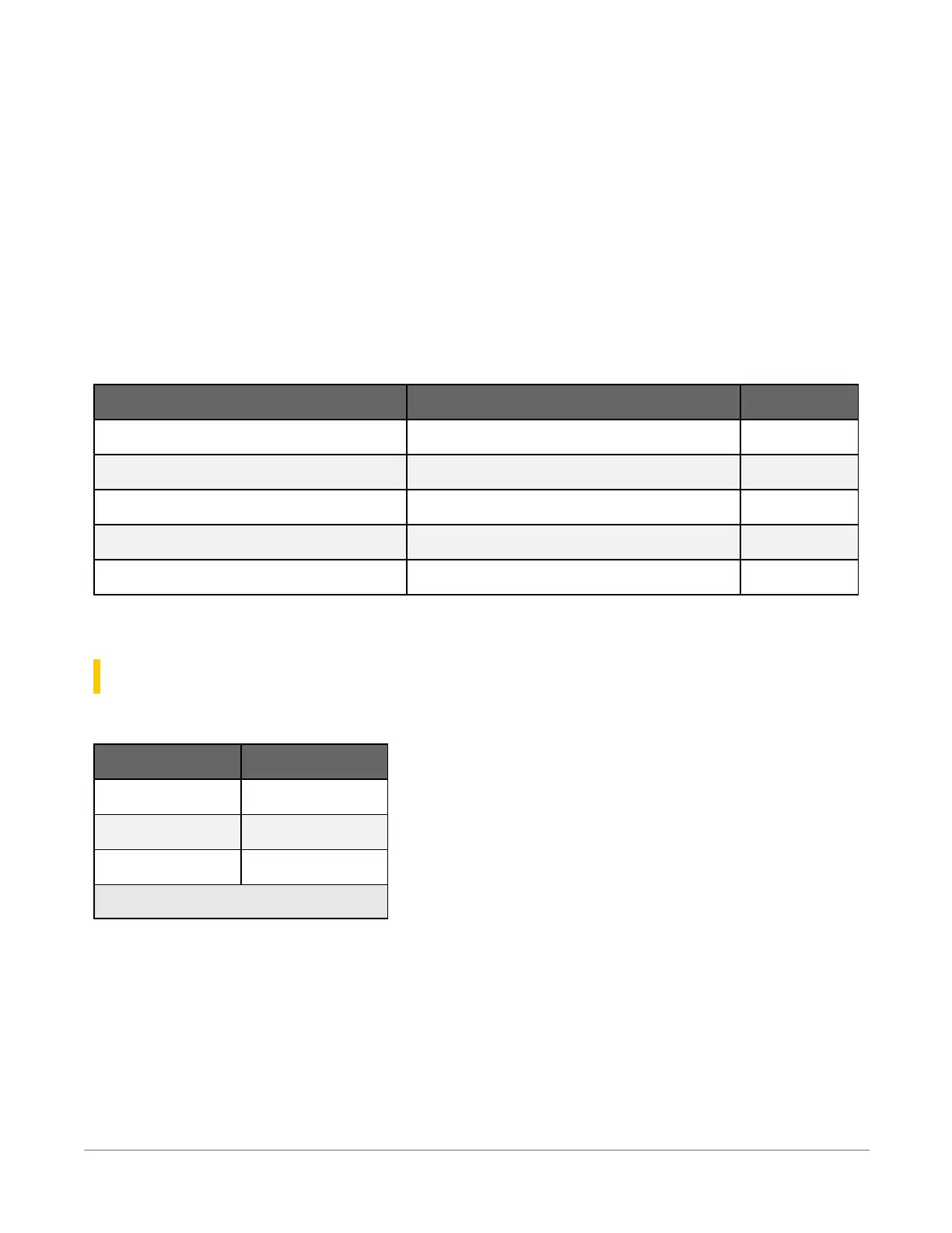
RF Average Additional Current Contribution at 12 VDC
-RF407, -RF412, -RF427 -RF422
Transmit < 80 mA 20 mA
Idle On 12 mA 9.5 mA
Idle 0.5 s Power Mode 4 mA 3.5 mA
Idle 1 s Power Mode 3 mA 2 mA
Idle 4 s Power Mode 1.5 mA 1.5 mA
See also Power output(p. 12).
24.4 Power output specifications
System power out limits (when powered with 12 VDC):
Temperature (°C) Current Limit
1
(A)
–40° 5.8
20° 3.7
70° 2.0
1
Limited by self-resetting thermal fuse
VX: Two independently configurable voltage terminals (VX1-VX2). VX outputs are produced by a
12-bit DAC. In this case, these terminals are regularly used with resistive-bridge measurements
(see Resistance measurements(p. 95) for more information). VX terminals can also be used to
supply a switched, regulated 5 VDC power source to power digital sensors and toggle control
lines.
24. CR300 series specifications242