SECTION 2
2-6
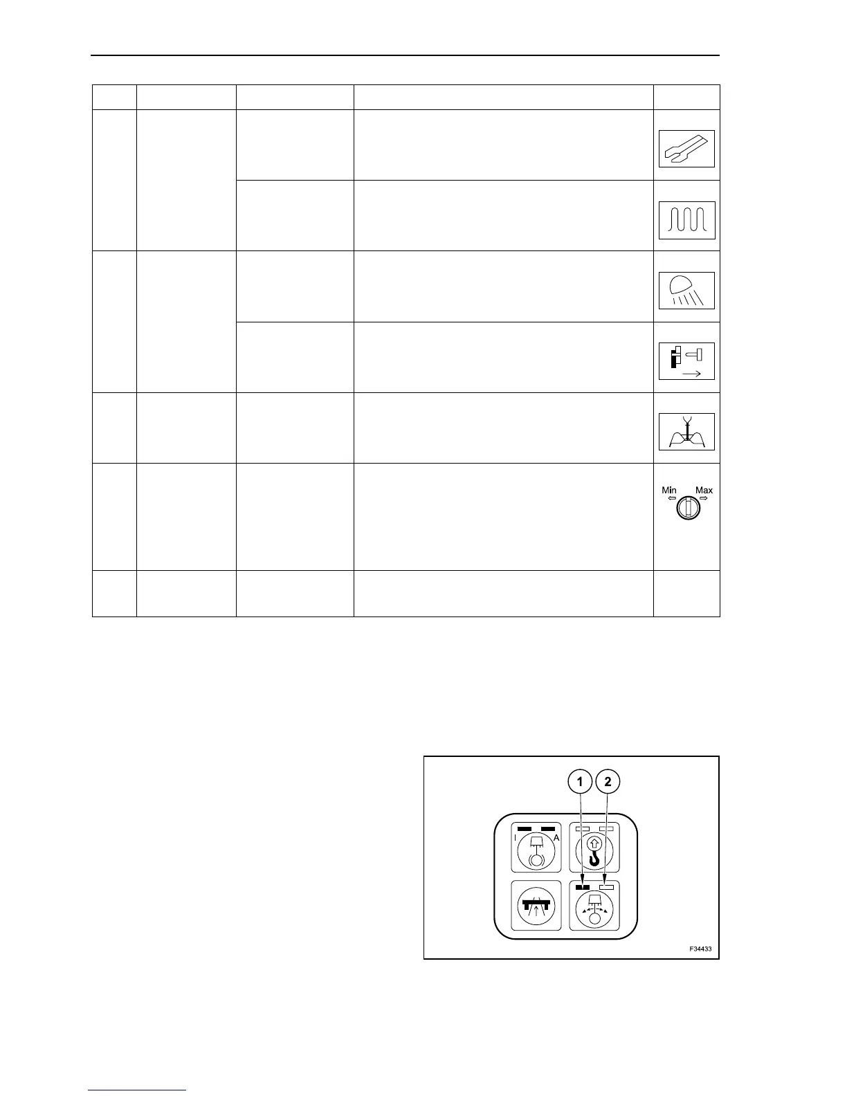
On the button of the key-pad modules and on the
switches are engraved symbols; they describe the
function of the button or switch below.
The button are activated by finger tip pressure. The
stroke of the buttons is short and at their activation a
tactile reaction takes place, warning the operator,
that the button has been pushed.
The buttons carry some LEDS (lights). The current
activation status of the button is indicated by lights.
The symbols on the buttons are backlighted, and
this feature activates automatically as soon as the
ignition key is set to “I” (ignition ON).
By activating repeatedly the buttons, different acti-
vation status can be achieved.
Some switches may have two lights: normally they
have a left light (1) and a right light (2).
Some switches are assigned to special attach-
ments. They are installed only on a machine with
special attachments.
30 Switch
Hydraulic Shears
(optional)
Activation: press the button face with no symbol.
Deactivation: press the button face with the
symbol.
Frequency
switching
(optional)
Activation: press the button face with no symbol.
Deactivation: press the button face with the
symbol.
31 Switch
Rear working
floodlamps
(optional)
Activation: press the button face with no symbol.
Deactivation: press the button face with the
symbol.
Quick coupler
(optional)
Activation: press the button face with no symbol.
Deactivation: press the button face with the
symbol.
32 Switch
Clamshell
opening/closing
The opening/closing speed of the clamshell is
determined by pre-set values. The speed
reduction is optional.
33 Potentiometer
Travel speed
limiting device
(Inching)
Set the maximum travel speed by keeping the
travel pedal pressed.
Adjustment while driving possible.
Left slewing: minimum.
Right slewing: maximum.
34 Ignition key
Activates and deactivates the electrical system.
Starting/Stopping the engine.
Ref. Description Operation Symbol
2