7-3
Cisco 4700 Series Application Control Engine Appliance Administration Guide
OL-11157-01
Chapter 7 Configuring Redundant ACE Appliances
Overview of Redundancy
Each FT group acts as an independent redundancy instance. When a switchover
occurs, the active member in the FT group becomes the standby member and the
original standby member becomes the active member. A switchover can occur for
the following reasons:
• The active member becomes unresponsive.
• A tracked host or interface fails (see the “Configuring Tracking and Failure
Detection” section).
• You enter the ft switchover command to force a switchover (see the “Forcing
a Failover” section).
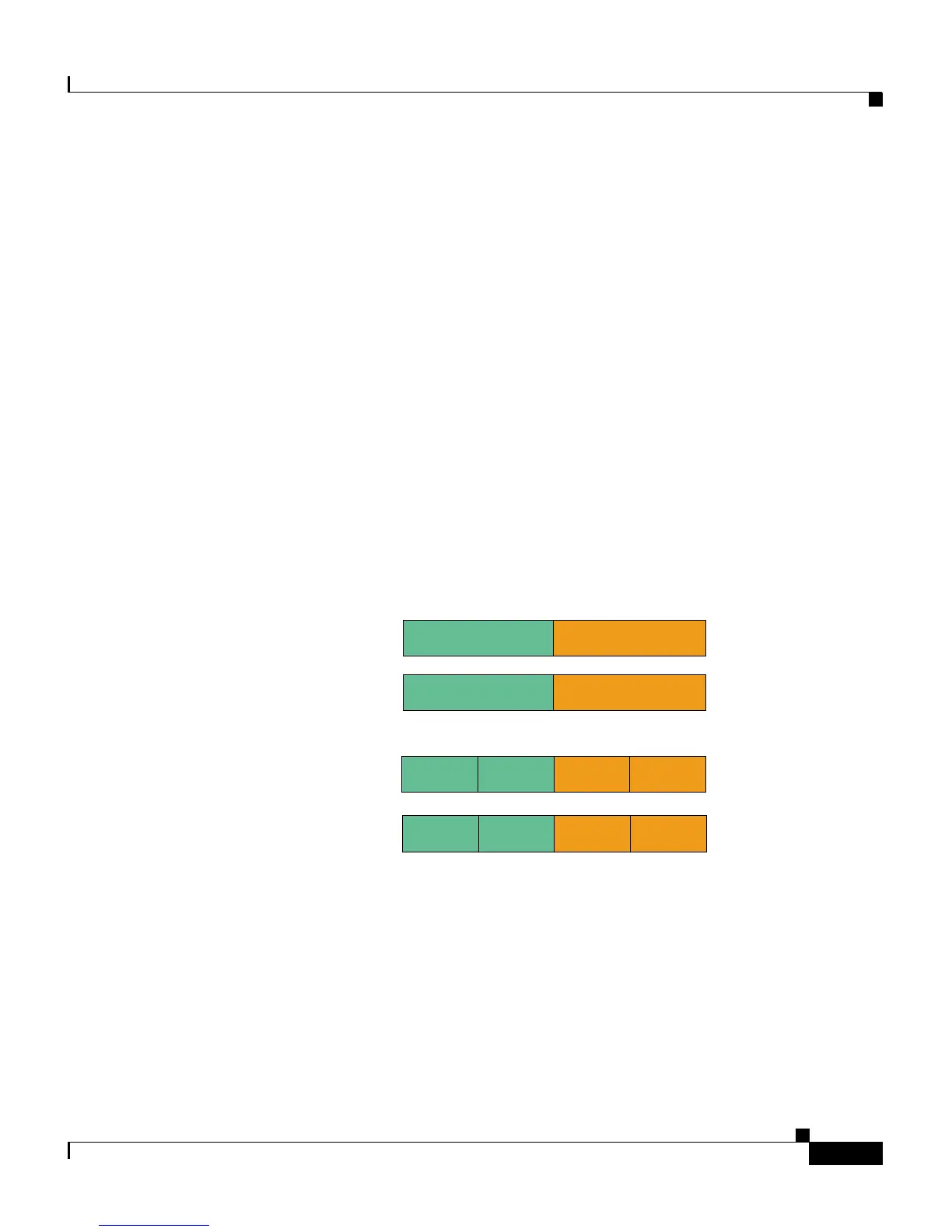
Figure 7-1 sh
ows two possible redundancy configurations, where N is the number
of ACEs configured for redundancy. The le
tters (A, B, C, and D) represent the
active contexts in each redundancy group, while the primed letters (A’, B’, C’, and
D’) are the standby contexts. The contexts are evenly distributed between the two
ACEs. You always configure the active and the standby contexts on different
ACEs.
Figure 7-1 Even Distribution of Contexts
153639
A
B’
B
A’
A B C’
D’
C D A’
B’
N=2
# redundant groups
=2
N=2
# redundant groups
=4
 Loading...


