5-24
Catalyst 2950 Desktop Switch Software Configuration Guide
78-11380-03
Chapter 5 Clustering Switches
Using SNMP to Manage Switch Clusters
Using SNMP to Manage Switch Clusters
When you first power on the switch, SNMP is enabled if you enter the IP information by using the setup
program and accept its proposed configuration. If you did not use the setup program to enter the IP
information and SNMP was not enabled, you can enable it as described in the “Configuring SNMP”
sectiononpage6-12. On Catalyst 1900 and Catalyst 2820 switches, SNMP is enabled by default.
When you create a cluster, the command switch manages the exchange of messages between member
switches and an SNMP application. The cluster software on the command switch appends the member
switch number (@esN,whereN is the switch number) to the first configured read-write and read-only
community strings on the command switch and propagates them to the member switch. The command
switch uses this community string to control the forwarding of gets, sets, and get-next messages between
the SNMP management station and the member switches.
Note When a cluster standby group is configured, the command switch can change without your knowledge.
Use the first read-write and read-only community strings to communicate with the command switch if
there is a cluster standby group configured for the cluster.
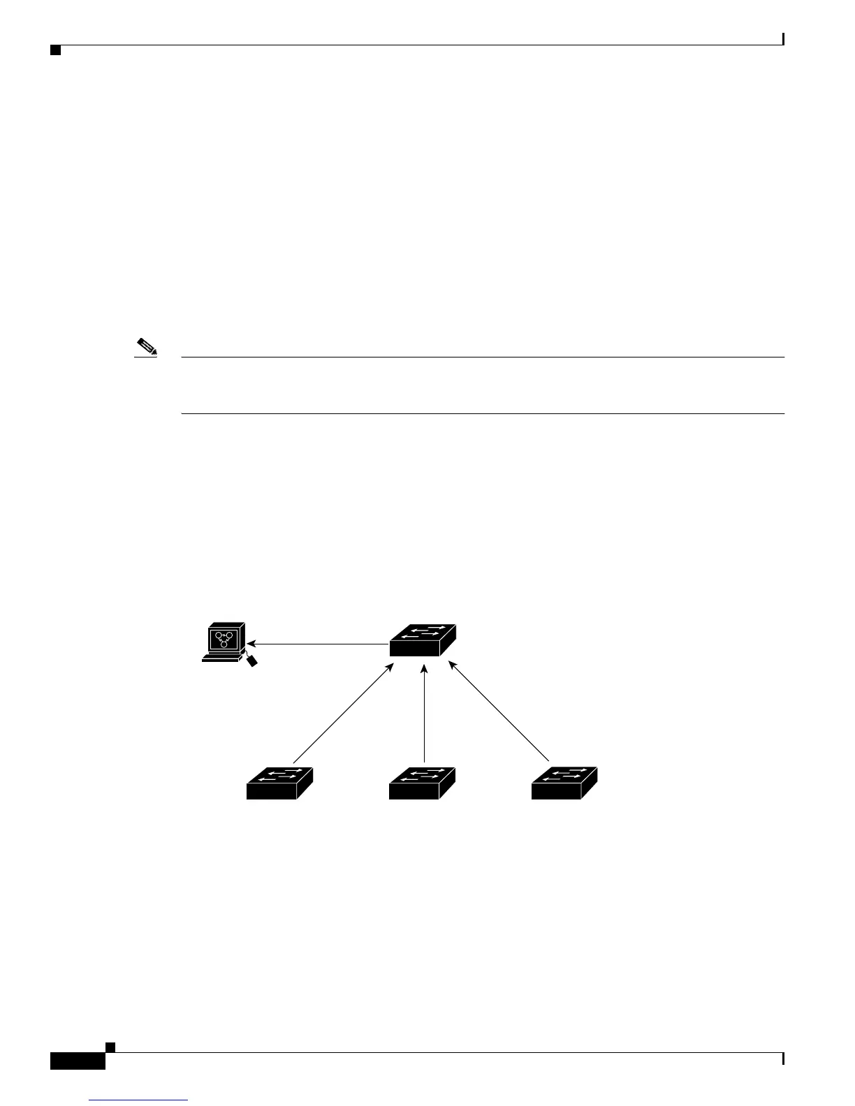
If the member switch does not have an IP address, the command switch redirects traps from the member
switch to the management station, as shown in Figure 5-12. If a member switch has its own IP address
and community strings, the member switch can send traps directly to the management station, without
going through the command switch.
If a member switch has its own IP address and community strings, they can be used in addition to the
access provided by the command switch. For more information about SNMP and configuring community
strings, see the “Configuring SNMP” section on page 6-12.
Figure 5-12 SNMP Management for a Cluster
Trap
Trap
Trap
Command switch
Trap 1, Trap 2, Trap 3
Member 1 Member 2 Member 3
33020
SNMP Manager