6-2
Catalyst 2950 Desktop Switch Software Configuration Guide
78-11380-03
Chapter 6 Configuring the System
Changing IP Information
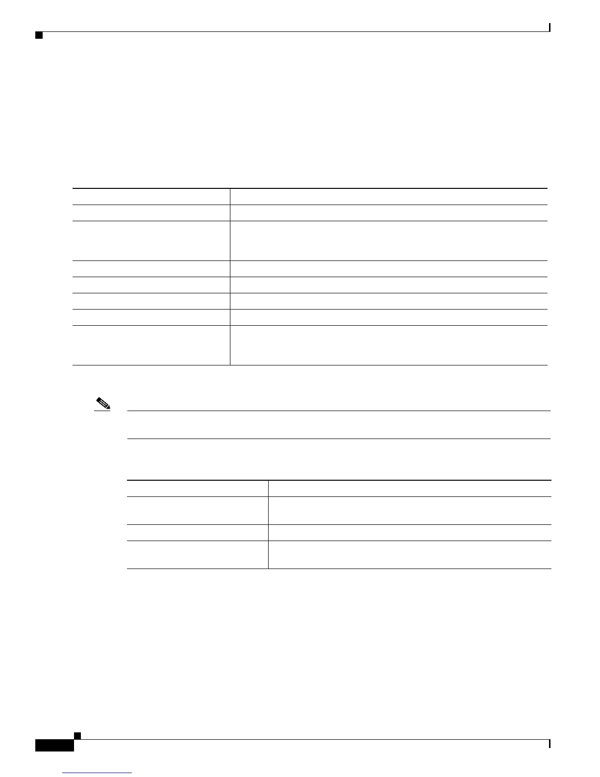
Manually Assigning and Removing Switch IP Information
You can manually assign an IP address, mask, and default gateway to the switch. The mask identifies the
bits that denote the network number in the IP address. When you use the mask to subnet a network, the
mask is then referred to as a subnet mask. The broadcast address is reserved for sending messages to all
hosts. The CPU sends traffic to an unknown IP address through the default gateway.
Beginning in privileged EXEC mode, follow these steps to enter the IP information:
Use this procedure to remove the IP information from a switch.
Note Using the no ip address command in configuration mode disables the IP stack as well as removes the
IP information. Cluster members without IP addresses rely on the enabled IP stack.
Beginning in privileged EXEC mode, follow these steps to remove an IP address:
Using DHCP-Based Autoconfiguration
The Dynamic Host Configuration Protocol (DHCP) provides configuration information to Internet hosts
and internetworking devices. With DHCP-based autoconfiguration, your switch (DHCP client) can be
automatically configured during bootup with IP address information and a configuration file that it
receives during DHCP-based autoconfiguration.
Command Purpose
Step 1
configure terminal Enter global configuration mode.
Step 2
interface vlan 1 Enter interface configuration mode, and enter the VLAN to which the IP
information is assigned. VLAN 1 is the default management VLAN, but you
can configure any VLAN from 1 to 1001.
Step 3
ip address ip_address subnet_mask Enter the IP address and subnet mask.
Step 4
exit Return to global configuration mode.
Step 5
ip default-gateway ip_address Enter the IP address of the default router.
Step 6
end Return to privileged EXEC mode.
Step 7
show running-config Verify that you entered the information was entered correctly by displaying
the running configuration. If the information is incorrect, repeat the
procedure.
Command Purpose
Step 1
no ip address ip_address
subnet_mask
Remove the IP address and subnet mask.
Step 2
end Return to privileged EXEC mode.
Step 3
show running-config Verify that you entered the information was removed by displaying
the running configuration.

 Loading...


