10-10
Catalyst 2950 Desktop Switch Software Configuration Guide
78-11380-03
Chapter 10 Configuring the Switch Ports
Understanding the EtherChannel
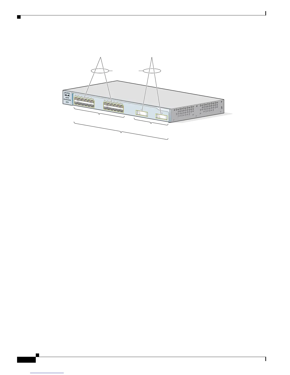
Figure 10-2 Relationship of Physical Ports, Logical Port Channels, and Channel Groups
After you configure an EtherChannel, configuration changes applied to the port-channel interface apply
to all the physical interfaces assigned to the port-channel interface. Configuration changes applied to the
physical interface affect only the interface where you apply the configuration. To change the parameters
of all ports in an EtherChannel, apply configuration commands to the port-channel interface, for
example, Spanning Tree Protocol (STP) commands or commands to configure a Layer 2 EtherChannel
as a trunk.
Understanding the Port Aggregation Protocol
The Port Aggregation Protocol (PAgP) facilitates the automatic creation of EtherChannels by
exchanging packets between Ethernet interfaces. By using PAgP, the switch learns the identity of
partners capable of supporting PAgP and learns the capabilities of each interface. It then dynamically
groups similarly configured interfaces into a single logical link (channel or aggregate port); these
interfaces are grouped based on hardware, administrative, and port parameter constraints. For example,
PAgP groups the interfaces with the same speed, duplex mode, native VLAN, VLAN range, and trunking
status and type. After grouping the links into an EtherChannel, PAgP adds the group to the spanning tree
as a single switch port.
PAgP Modes
Table 10-1 shows the user-configurable EtherChannel modes for the channel-group interface
configuration command: on, auto,anddesirable. Switch interfaces exchange PAgP packets only with
partner interfaces configured in the auto or desirable modes; interfaces configured in the on mode do
not exchange PAgP packets.
65636
SY
ST
R
PS
DU
P
LX
M
O
D
E
S
PEE
D
UT
IL
STA
T
Catalyst 2950
SE
RIES
1
X
2
X
1
1
X
1
2
X
1
2
3
4
5
6
7
8
9
1
0
1
1
1
2
1
1
3
X
1
4
X
2
3
X
2
4
X
1
3
1
4
1
5
1
6
1
7
1
8
1
9
2
0
2
1
2
2
2
3
2
4
2
10/100 ports
GBIC module
slots
Physical
ports
Logical
port-channel
Channel-group
binding
Logical
port-channel

 Loading...


