97
Configuring Switch Clusters
How to Plan for Switch Clustering
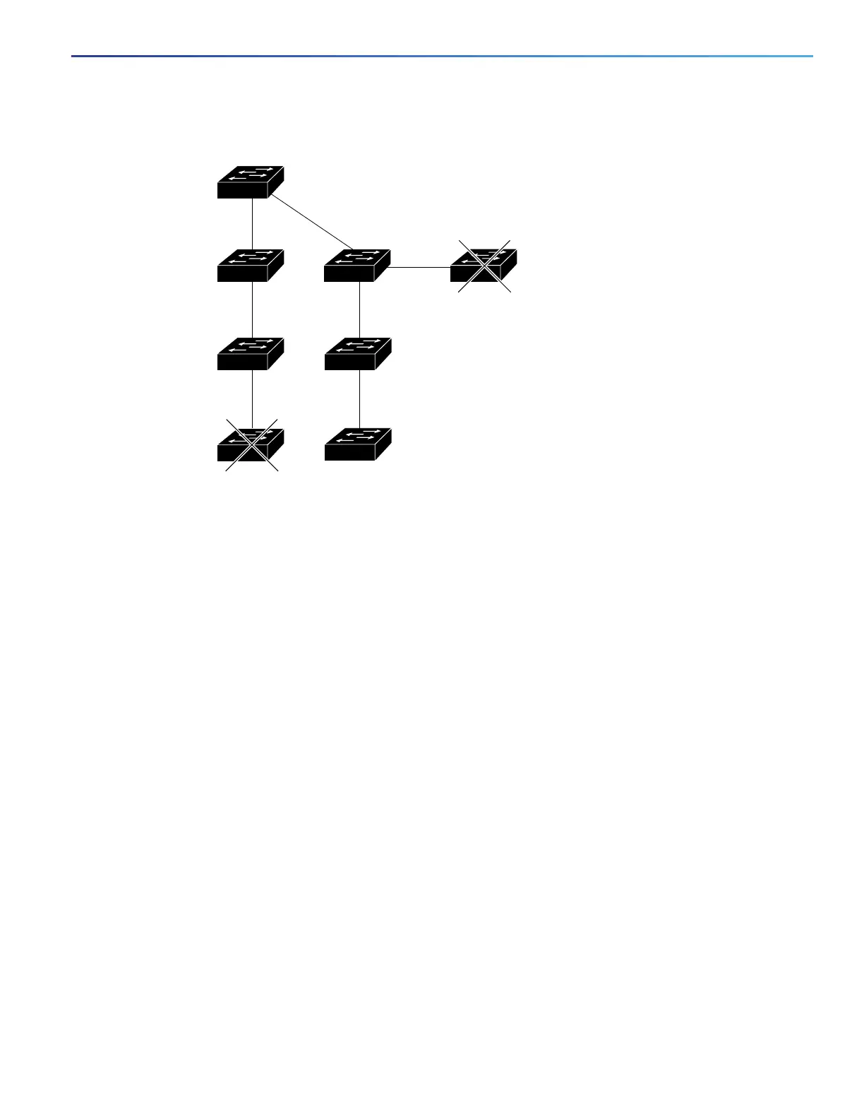
Figure 9 Discovery Through Different VLANs
Discovery Through Different Management VLANs
Catalyst 2970, Catalyst 3550, Catalyst 3560, or Catalyst 3750 cluster command switches can discover and manage
cluster member switches in different VLANs and different management VLANs. As cluster member switches, they must
be connected through at least one VLAN in common with the cluster command switch. They do not need to be connected
to the cluster command switch through their management VLAN. The default management VLAN is VLAN 1.
Note: If the switch cluster has a Catalyst 3750 or 2975 switch or has a switch stack, that switch or switch stack must be
the cluster command switch.
The cluster command switch and standby command switch in Figure 11 on page 98 (assuming they are Catalyst 2960,
Catalyst 2970, Catalyst 2975, Catalyst 3550, Catalyst 3560, or Catalyst 3750 cluster command switches) have ports
assigned to VLANs 9, 16, and 62. The management VLAN on the cluster command switch is VLAN 9. Each cluster
command switch discovers the switches in the different management VLANs except these:
Switches 7 and 10 (switches in management VLAN 4) because they are not connected through a common VLAN
(meaning VLANs 62 and 9) with the cluster command switch
Switch 9 because automatic discovery does not extend beyond a noncandidate device, which is switch 7
Discovery Through Routed Ports
Note: The LAN Base image supports static routing.
If the cluster command switch has a routed port (RP) configured, it discovers only candidate and cluster member
switches in the same VLAN as the routed port.
The Layer 3 cluster command switch in Figure 10 on page 98 can discover the switches in VLANs 9 and 62 but not the
switch in VLAN 4. If the routed port path between the cluster command switch and cluster member switch 7 is lost,
connectivity with cluster member switch 7 is maintained because of the redundant path through VLAN 9.
VLAN 62
VLAN 62
VLAN 16
VLAN trunk 9,16
Command device
VLAN 50
VLAN trunk 9,16
VLAN trunk 4,16
101322