432
Configuring IGMP Snooping and MVR
Information About IGMP Snooping and MVR
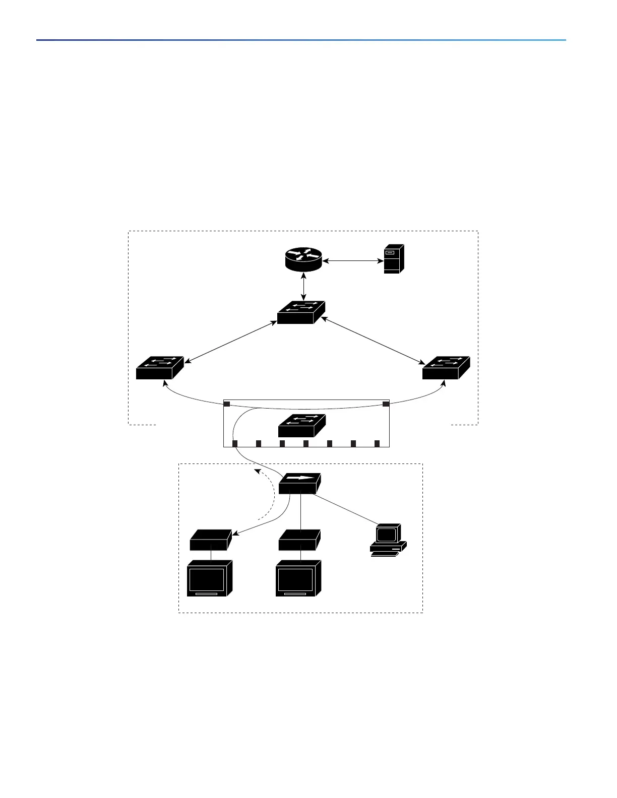
MVR in a Multicast Television Application
In a multicast television application, a PC or a television with a set-top box can receive the multicast stream. Multiple
set-top boxes or PCs can be connected to one subscriber port, which is a switch port configured as an MVR receiver
port. Figure 67 on page 432 is an example configuration. DHCP assigns an IP address to the set-top box or the PC. When
a subscriber selects a channel, the set-top box or PC sends an IGMP report to Switch A to join the appropriate multicast.
If the IGMP report matches one of the configured IP multicast group addresses, the switch CPU modifies the hardware
address table to include this receiver port and VLAN as a forwarding destination of the specified multicast stream when
it is received from the multicast VLAN. Uplink ports that send and receive multicast data to and from the multicast VLAN
are called MVR source ports.
Figure 67 Multicast VLAN Registration Example
When a subscriber changes channels or turns off the television, the set-top box sends an IGMP leave message for the
multicast stream. The switch CPU sends a MAC-based general query through the receiver port VLAN. If there is another
set-top box in the VLAN still subscribing to this group, that set-top box must respond within the maximum response time
specified in the query. If the CPU does not receive a response, it eliminates the receiver port as a forwarding destination
for this group.
SP1
Multicast
data
Multicast
data
Customer
premises
Multicast VLAN
SP
SP
RP = Receiver Port
SP = Source Port
Note: All source ports belong to
the multicast VLAN.
Hub
TV
data
Set-top boxSet-top box
TV TV
PC
SP
SP
SP
SP
IGMP join
Cisco router
Multicast
server
Switch B
SP2
RP1 RP2 RP3 RP4 RP5 RP6 RP7
101364
Switch A