25
Configuring Interfaces
Understanding Interface Types
on power on the PoE port, the switch does not police the real-time power consumption of the device, and the device
can consume more power than the maximum allocate d amount, which could adversely affect the switch and the devices
connected to the other PoE ports.
Because the switch supports internal power supplies and the Cisco Redundant Power System 2300 (also referred to as
the RPS 2300), the total amount of power available for the powered devices varies depending on the power supply
configuration.
The switch supports dual power supplies. If a power supply is removed or fails and the switch does not have enough
power for the powered devices, the switch first denies power to low-priority ports in descending order of port numbers,
and then to high priority ports in descending numbers. The total available PoE power is 65 watts per power supply.
If a power supply is removed and replaced by a new power supply with less power and the switch does not have
enough power for the powered devices, the switch denies power to the PoE ports in auto mode in descending order
of the port numbers. If the switch still does not have enough power, the switch then denies power to the PoE ports
in static mode in descending order of the port numbers.
If the new power supply supports more power than the previous one and the switch now has more power available,
the switch grants power to the PoE ports in static mode in ascending order of the port numbers. If it still has power
available, the switch then grants power to the PoE ports in auto mode in ascending order of the port numbers.
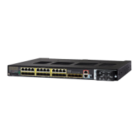
Dual-Purpose Ports on IE 4000
Each dual-purpose port is considered a single interface with dual front ends (an RJ-45 connector and an SFP module
connector). The dual front ends are not redundant interfaces; the switch activates only one connector of the pair.
By default, dual-purpose ports are user-network interfaces (UNIs) and SFP-only module ports are network node
interfaces (NNIs). TBy default, the switch dynamically selects the dual-purpose port media type that first links up.
However, you can use the media-type interface configuration command to manually select the RJ-45 connector or the
SFP module connector.
Each dual-purpose port has two LEDs: one shows the status of the SFP module port, and one shows the status of the
RJ-45 port. The port LED is on for whichever connector is active. For more information about the LEDs, see the
hardware installation guide.
Connecting Interfaces
Devices within a single VLAN can communicate directly through any switch. Ports in different VLANs cannot exchange
data without going through a routing device. With a standard Layer 2 switch, ports in different VLANs have to exchange
information through a router.
By default, the switch provides VLAN isolation between UNIs or ENIs. UNIs and ENIs cannot exchange traffic unless they
are changed to NNIs or assigned to a UNI-ENI community VLAN.
By using the switch with routing enabled, when you configure both VLAN 20 and VLAN 30 with an SVI to which an IP
address is assigned, packets can be sent from Host A to Host B directly through the switch with no need for an external
router (Figure 1 on page 26).
 Loading...
