1. Hold the handle and push it down
to close the threshing unit top cov-
er.
2. Fix it with the xing handle.
HOW
TO FIX THRESHING CYLINDER
B55O889A
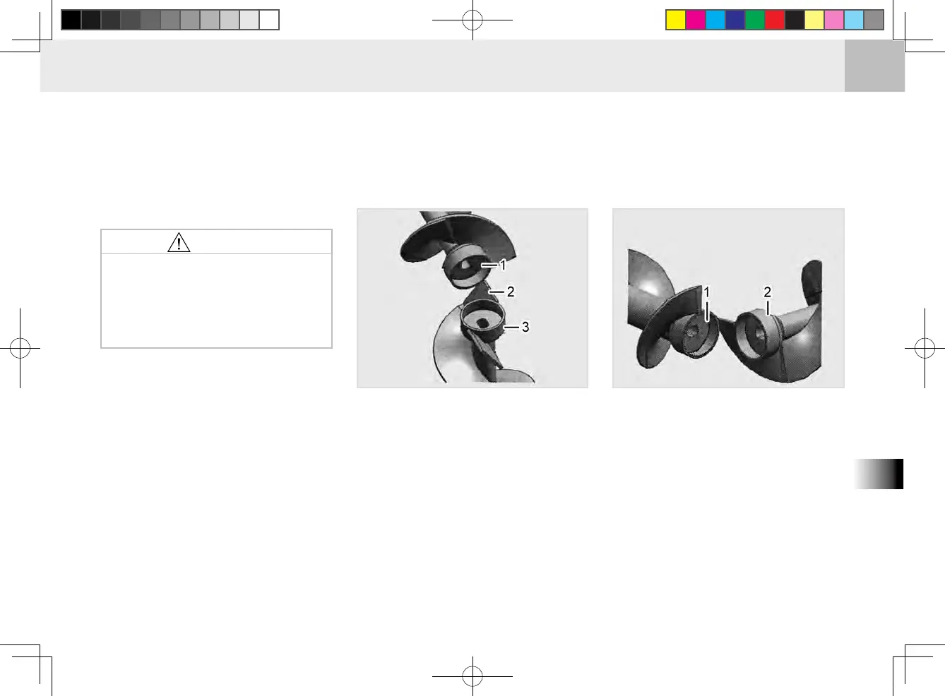
CAUTIONS FOR AUGER INSTALLATION
(1) Contact Auger Assembly (Bottom) Marking
(2) Main Blade
(3) Unloader Auger Shaft Assembly 1 (End)
B55O890A
(1) Unloader Auger 2 Assembly (Bottom) Marking
(2) Contact Auger Assembly (End)
When installing the unloader auger
2 assembly, its rod part marked as
(bottom) should face the contact
auger assembly and should be 90°
behind the blade direction of the con-
tact auger assembly.
If reaping with the xing han-
dle not in the closing position,
the threshing unit frame can
be deformed, resulting in poor
reaping performance.
•
CAUTION
INSTALLING UNLOADER AUGER
SHAFT ASSEMBLY 1 AND CON-
TACT AUGER ASSEMBLY
When installing the contact auger
assembly, its boss 2 part marked as
(bottom) should face the unloader
auger shaft assembly and should be
90° behind the main blade direction
of the unloader auger shaft.
IN
STALLING CONTACT AUGER
ASSEMBLY AND UNLOADER AU-
GER 2
ASSEMBLY