8
-
PB
MAINTENANCED
SF75GT
8
-
54
B55O8A6B
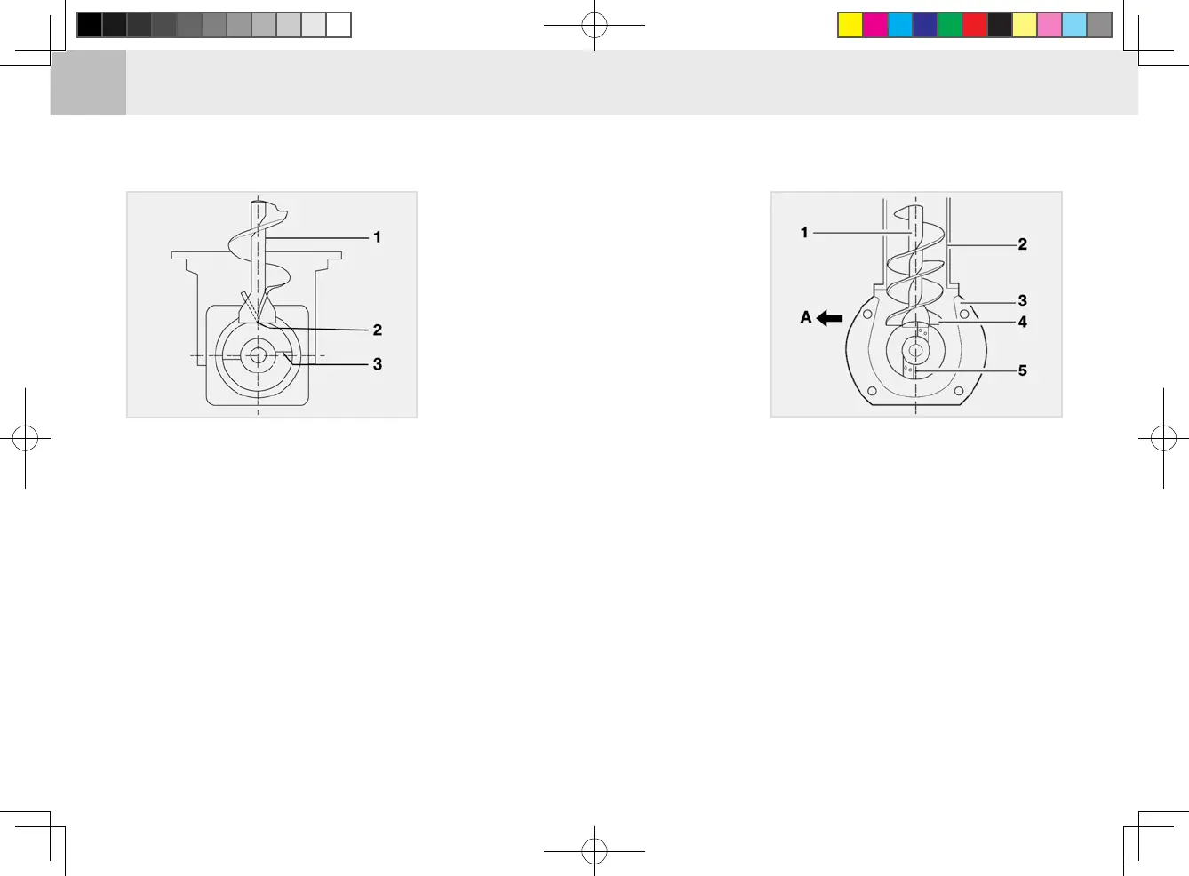
(1) Vertical Auger Shaft
(2) Vertical Auger Case
(3) No.1 Bevel Case
(4) Front End Of Vertical Auger
(5) Rear End Of No. 1 Discharge Wing
(A) Front Of Vehicle Body
3. After installation, rotate the verti-
cal auger one turn to check for any
interference.
B55O8A5B
(1) No.1 Auger Shaft
(2) Rear End Of No.1 Discharge Wing
(3) Front End Of Vertical Auger
INSTALLING VERTICAL AUGER SHAFT
CAUTIONS FOR VERTICAL AUGER INSTALLATION
When removing and reinstalling the
vertical auger, install it to the follow-
ing position:
1.
Set the rear end of the No. 1 dis-
charge wing in the center of the
vehicle longitudinally.
2. Set the front end of the vertical
auger parallel to the vehicle body
longitudinally.