RS20iInstallationandOperatingGuide
Page 109
RS20i Installation & Operating Guide Document # 9301H52900 Ver. 1.02
Setup > Test
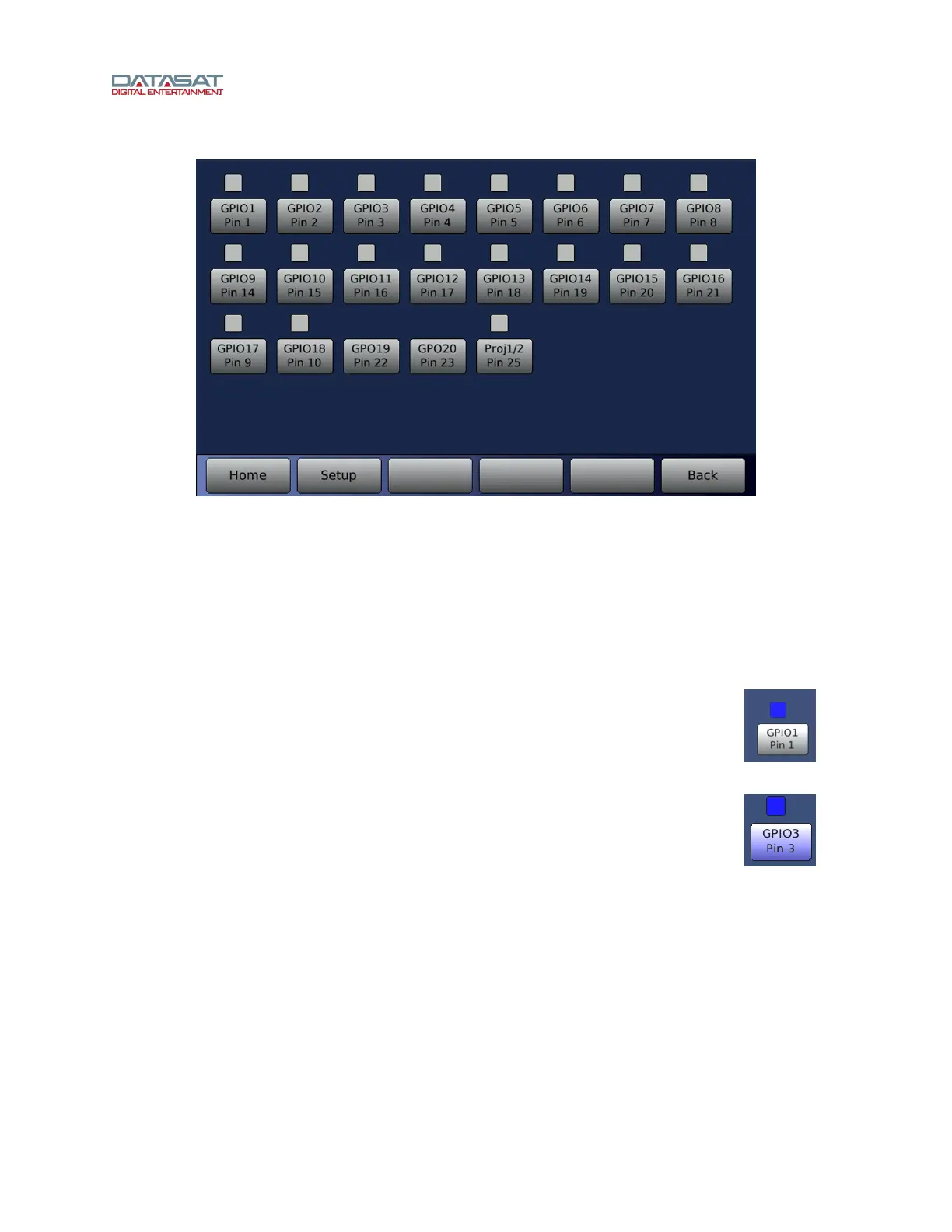
Figure 76. Automation Test
The screen displays a series of automation buttons, one for each automation output signal
(GPO), and an indicator above it that represents the signal input (GPI) state. Note: GPO19
and 20 are outputs only and do not have an input indicator. The input indicator is white when
the signal is high or just unconnected. The input indicator turns blue when there is a low
signal applied to the pin.
To verify that the RS20i is properly receiving an input from an external source you would need to
make the external device send a low signal on that pin. Then confirm that the signal is received
by the RS20i by checking if the corresponding indicator turns blue.
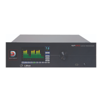
Example: The button at right illustrates when receiving an input signal on GPIO1.
To test an output signal, press the Automation Button. It creates a low pulse on
the corresponding output pin. The button turns blue in conjunction with the output
signal being low.
Example: The button at right shows GPIO3 has been selected. Note that the
indicator will also turn blue after pressing the button, indicating that it is reading
the low signal on the same pin.