RS20iInstallationandOperatingGuide
Page 22
RS20i Installation & Operating Guide Document # 9301H52900 Ver. 1.02
2.3 RS20i Rear Panel Connections
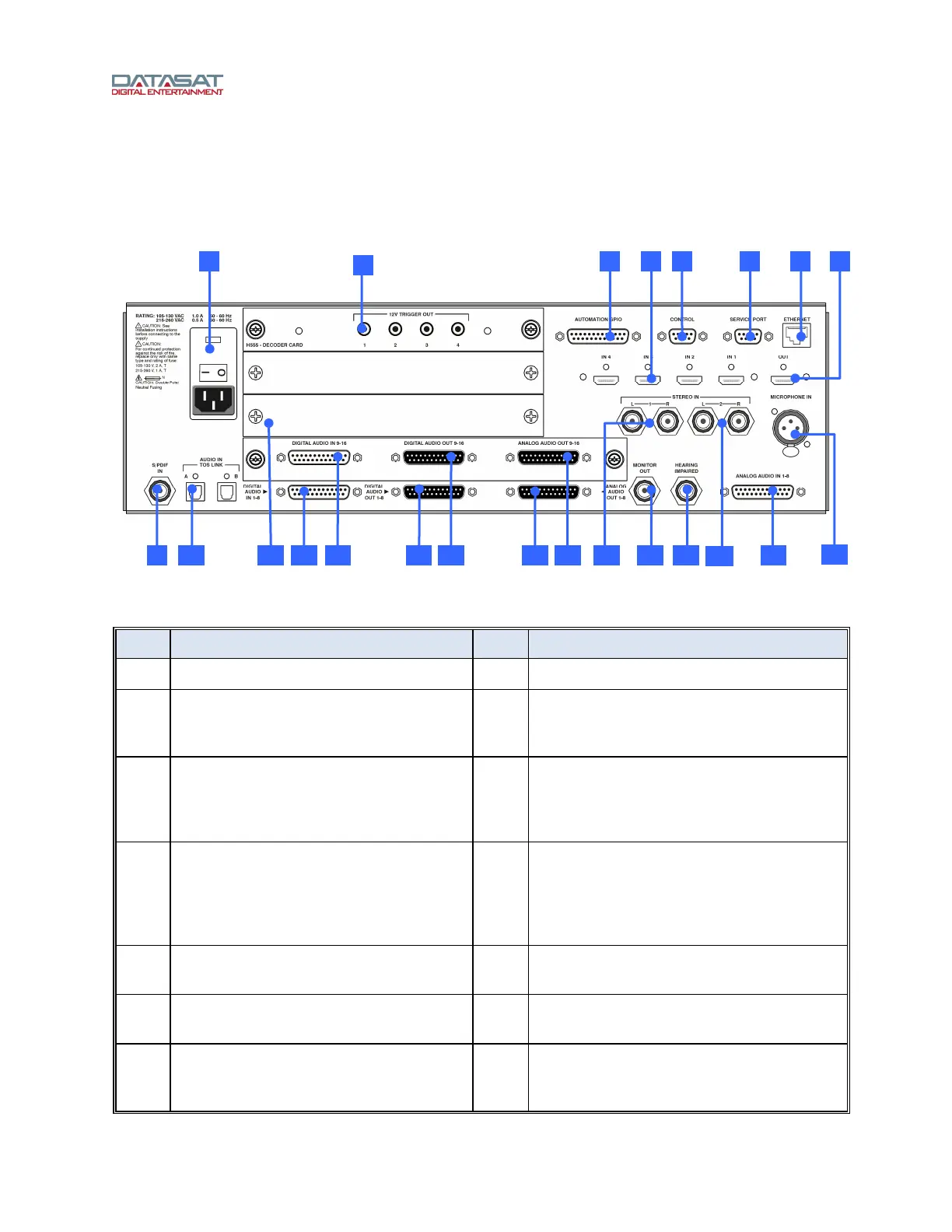
Figure 9 shows the rear panel of the RS20i and Table 3 provides a description of each connector. For
specific information on the pin-outs of each connector, please see Appendix A of this manual.
Figure 9. RS20i Rear Panel
Table 3. RS20i Rear Panel Connections
Item Description Item Description
1 Power Entry Module/Power Switch 12 Digital Audio In (CH 1 – 8) – DB25F
2 12 volt trigger out (4) – 3.5mm mono
jacks. Used for automation functions
such as powering on amplifiers.
13 Digital Audio In (CH 9 – 16) – DB25F
3 Automation GPIO – DB25F
(sends/receives pulses to/from
automation system or other devices)
14 Digital Audio Out (CH 1 – 8) – DB25M (for
use in environments with amplifiers,
routers, or crossovers that can handle
digital in)
4 HDMI In (4) 15 Digital Audio Out (CH 9 – 16) – DB25M
(for use in environments with amplifiers,
routers, or crossovers that can handle
digital in – see Digital Out Setup, page 86,
to
configure)
5 Control (RS232) – DB9F (serial
automation control)
16 Analog Audio Out (CH 1 – 8) – DB25M
(connect to amplifiers)
6 Service Port (RS232)– DB9F (used for
factory testing)
17 Analog Audio Out (CH 9 – 16) – DB25M
(connect to amplifiers)
7 Ethernet – RJ45F (Network connection
for VNC and software updates when
connected to the internet)
18 Stereo Input 1 – Two RCA L/R Single
ended analog inputs
229 11 12 10 13 14 15
23
1 3 5 6 84 7
21
18
20 1916 17
2