RS20i Installation and Operating Guide Page A-8
Appendix A. Connector Pin-outs Document #: 9301H52900 Ver. 1.02
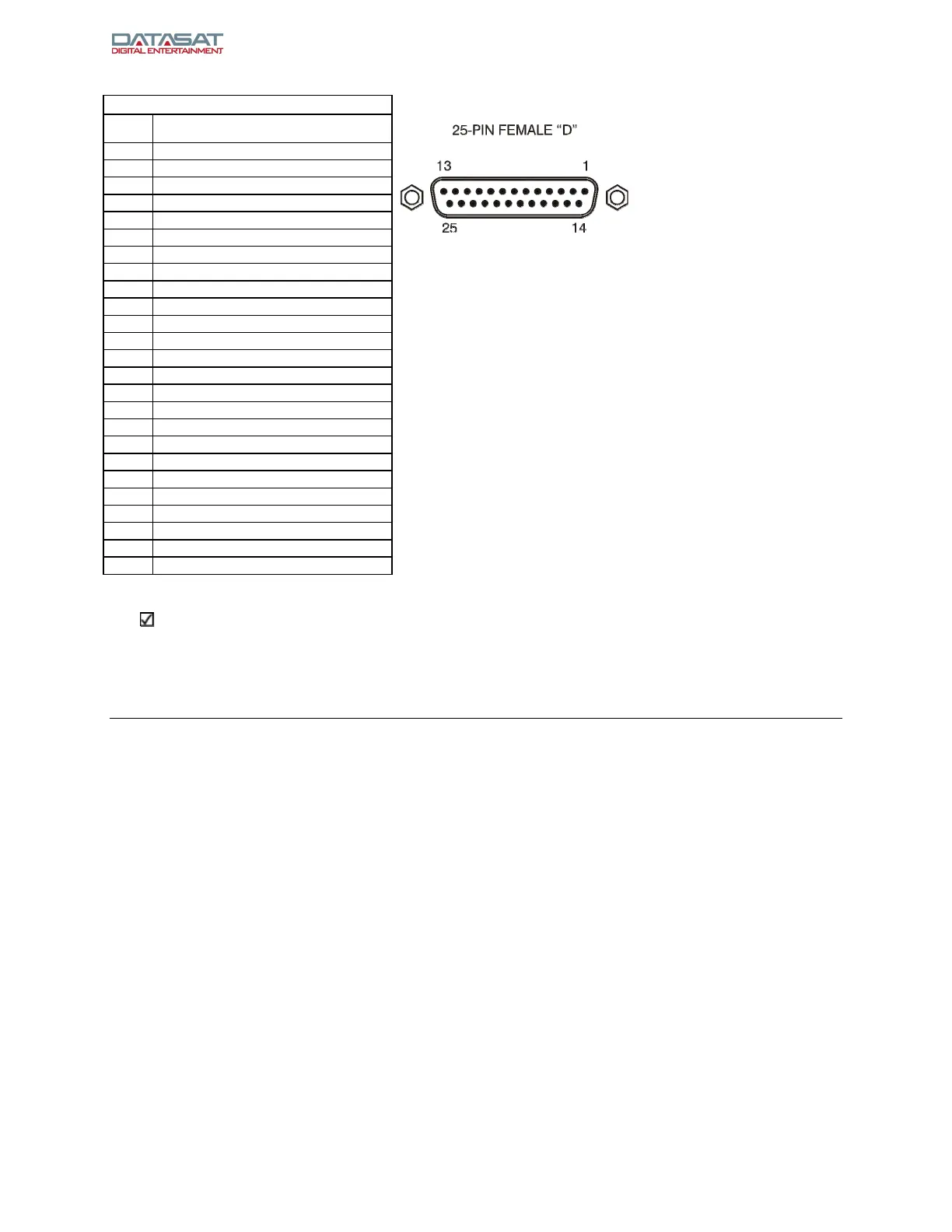
ANALOG AUDIO IN – DB25F
Pin Description
1 CHANNEL 1 (-)
2 CHANNEL 6 (+)
3 CHANNEL 6 (-)
4 CHANNEL 5 (-)
5 CHANNEL 8 (-)
6 CHANNEL 2 (-)
7 CHANNEL 7 (-)
8 CHANNEL 3 (-)
9 GND
10 GND
11 GND
12 CHANNEL 4 (-)
13 GND
14 CHANNEL 1 (+)
15 CHANNEL 5 (+)
16 CHANNEL 8 (+)
17 CHANNEL 2 (+)
18 CHANNEL 7 (+)
19 GND
20 CHANNEL 3 (+)
21 N/C
22 GND
23 GND
24 CHANNEL 4 (+)
25 N/C
N/C = No connection
Note: RS20i Analog in and out channels are designed to be balanced, not single ended,
for highest sound quality. If wiring single ended, wire only to (+) and ground. The (-)
side of the channels should not be connected. Do not short the (-) sides of the channels
to ground, which will degrade sound quality and cause the RS20i to overheat.
 Loading...