RS20iInstallationandOperatingGuide
Page 70
RS20i Installation & Operating Guide Document # 9301H52900 Ver. 1.02
Control Description
Frequency: 20 Hz to 20kHz
Xvr ID
Output Channel ID: 0-8,L,M,H,W
Output Trim
Output Channel Trim
(-10.0 dB to 0.0 dB in .5dB increments)
The Output Trim may be used to balance the levels of crossover channels.
Note: The output channels are assigned one of the following letter IDs (Crossover
ID): W, L, M, H, and 0-9. This is used for reference for the output channel and
has no functional purpose at this time.
4.5.3.1 About Routing Crossovers
Crossover use can be attributed to the inability of most speaker drivers to reproduce the entire audio
spectrum smoothly and efficiently. Because of this, most speaker systems are comprised of several
drivers, each of which is dedicated to the reproduction of a specific range of frequencies.
These frequencies are routed to the appropriate driver by a crossover network. This device divides the
audio spectrum into two or more frequency bands. By doing this, each driver will receive only the
frequencies that it can reproduce properly. The crossover network also prevents potentially damaging
low-frequency energy from reaching the midrange or tweeter drivers.
This frequency division process is accomplished by using high-pass and low-pass filters. A high-pass
filter passes frequencies above a pre-determined frequency and attenuates those below. This pre-
determined frequency is called the crossover point. Conversely, a low-pass filter passes frequencies
below the crossover point and attenuates those above. By cascading high-pass and low-pass filters, a
band-pass filter can be realized. Filters of this type attenuate all frequencies outside of the pass-band
created by the high and low-pass filters.
The rate at which the attenuating process takes place is dependent upon the slope of the crossover. A
typical slope for sound systems is 24dB/octave. Higher numbers indicate a much steeper cutoff rate
while the lower numbers indicate a more gradual roll-off.
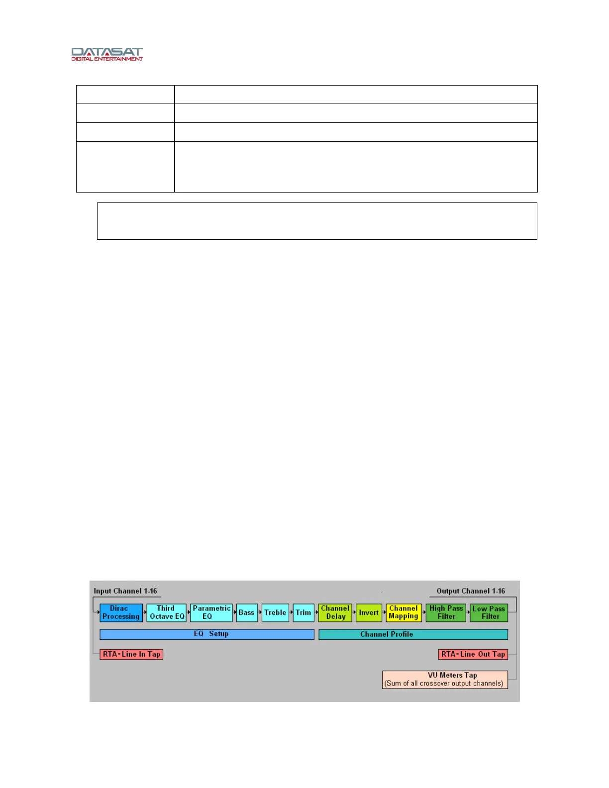
4.5.3.2 Signal flow
When implementing crossovers or implementing different internal routing on the RS20i, the internal
channel numbers do not match the output channel numbers. The following explanation clarifies how the
menus operate regarding the channel numbers.
From a user perspective, the channel mapping occurs near the last stage of the signal processing. Only
high pass and low pass filters are applied after the signal routing occurs. This is illustrated in the diagram
below.
Figure 47. Signal Processing Flow Diagram