EasyManuals Logo

DeLaval VMS 2008 User Manual

Default Icon
206 pages
To Next Page IconTo Next Page
To Previous Page IconTo Previous Page
Page #42 background imageLoading...
Page #42 background image
General description
DeLaval voluntary milking system VMS
94897201.pdf2007-12-18
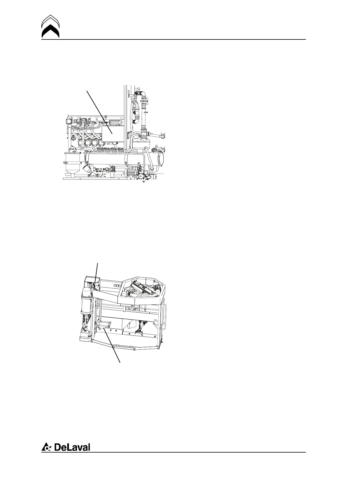
Power box
A 401A 402
A 403
A 404
A 621
A 622
FG
The power
box
The power box is placed in the upper part of
the cabinet. It contains motor protection for
the hydraulic pump and the milk pump and
a control fuse for internal wiring and
transformers.
Electrical box
The milking station is controlled by
programs executed in the station’s
computer, located in the electrical box.
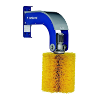
Feeding module
cd29900
Feeding
module
Manger
The feeding module consists of two main
parts:
Feed dispensers
Manger
34(198)

Table of Contents

Questions and Answers:

Question and Answer IconNeed help?

Do you have a question about the DeLaval VMS 2008 and is the answer not in the manual?

DeLaval VMS 2008 Specifications

General IconGeneral
BrandDeLaval
ModelVMS 2008
CategoryFarm Equipment
LanguageEnglish

Related product manuals