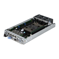
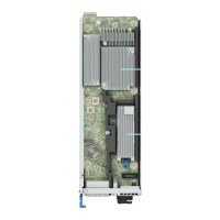
Figure 155. Installing the A100 NVlink Heatsink
NOTE:
There are six NVlink heatsinks installed on the GPU baseboard. Repeat steps 3 and 4 to install remaining NVlink
heatsinks.
5. Align and insert each rear heatsink on the GPU socket.
6. Using Phillips 1 screwdriver, tighten the screws securing rear heatsink in the order that is mentioned below:
a. Tighten the heatsink screws 3 turns each in the following order. Assembly order:1, 2, 3, 4.
b. Return to first screw and completely tighten it.
c. Completely tighten the remaining screws in the correct order.
NOTE:
There are four rear heatsinks installed on the GPU base board. Repeat steps 5 and 6 to install remaining rear
heatsinks.
NOTE: For GPU heatsink installation, ensure that the final torque value is 4 ± 4% lbf-in or 0.45 ± 4% N-m .
7. Align and insert each front heatsink on the GPU socket.
8. Using Phillips 1 screwdriver, tighten the screws securing front heatsink in the order that is mentioned below:
a. Tighten the heatsink screws 3 turns each in the following order. Assembly order:1, 2, 3, 4.
b. Return to first screw and completely tighten it.
c. Completely tighten the remaining screws in the correct order.
NOTE:
There are four front side heatsink installed on the GPU base board. Repeat steps 7 and 8 to install remaining
front heatsinks.
NOTE: For GPU heatsink installation, ensure that the final torque value is 4 ± 4% lbf-in or 0.45 ± 4% N-m .
Installing and removing system components 177

 Loading...


