Chapter 4 Parameters|
Revision Jan. 2009, 06EE, SW--PW V1.12/CTL V2.12 4-45
Group 1: Basic Parameters
01.00
Maximum Output Frequency (Fmax)
Unit: 0.01
Settings 50.00 to 600.0 Hz Factory Setting: 60.00
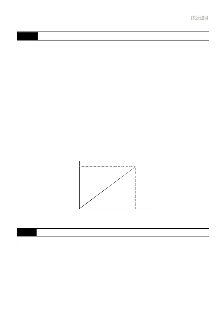
This parameter determines the AC motor drive’s Maximum Output Frequency. All the AC
motor drive frequency command sources (analog inputs 0 to +10V and 4 to 20mA) are scaled
to correspond to the output frequency range.
Please note that output frequency may be not in this setting range due to parameter setting:
1. Pr.00.10 is set to 0: when enabling Pr.07.03 (Slip Compensation) in V/f mode, it may be not
in this setting range.
2. Pr.00.10 is set to 1: The AC motor drive will auto compensate slip in vector mode, so it also
may be not within this setting range.
Related parameters: 00.10 (Control Method), 04.12(Min AVI Frequency), 04.14(Max AVI
Frequency), 04.16(Min ACI Frequency), 04.18(Max ACI Frequency), 04.19(ACI/AVI2
Selection), 04.21(Min AVI2 Frequency), 04.23(Max AVI2 Frequency) and 07.03(Slip
Compensation (Used without PG) (Motor 0))
V/F曲線
Output
Frequency
Analog Input
Signal
0V(4mA)
10V(20mA)
01.00
Max. Output
Frequency
01.01 Maximum Voltage Frequency (Fbase) (Motor 0) Unit: 0.01
Settings 0.10 to 600.0Hz Factory Setting: 60.00
This value should be set according to the rated frequency of the motor as indicated on the
motor nameplate. Maximum Voltage Frequency determines the v/f curve ratio. For example, if
the drive is rated for 460 VAC output and the Maximum Voltage Frequency is set to 60Hz, the
drive will maintain a constant ratio of 7.66 V/Hz (460V/60Hz=7.66V/Hz). This parameter value
must be equal to or greater than the Mid-Point Frequency (Pr.01.03).