Chapter 4 Parameters|
Revision Jan. 2009, 06EE, SW--PW V1.12/CTL V2.12 4-77
This parameter sets the count value of the internal counter. To increase the internal counter,
one of Pr.04.05 to 04.08 should be set to 12. Upon completion of counting, the specified output
terminal will be activated. (Pr.03.00 to Pr.03.01 set to 11).
It can be used as an indication for the AC motor drive run in low speed to stop.
Related parameters: Pr.03.00(Multi-function Output Relay (RA1, RB1, RC1)), Pr.03.01(Multi-
function Output Terminal MO1), Pr.04.05(Multi-function Input Terminal (MI3)), Pr.04.06(Multi-
function Input Terminal (MI4)), Pr.04.07(Multi-function Input Terminal (MI5)) and
Pr.04.08(Multi-function Input Terminal (MI6)
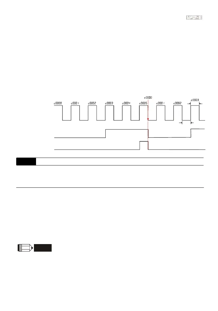
Example: The timing diagram for Pr.03.05=5 and Pr.03.06=3
Te r mi n a l C o u nt Va l u e
(Pr. 03.00~Pr. 03.01=10)
Preliminary Count Value
(Pr. 03.00~Pr. 03.01=11)
Display
(Pr.00.04=1)
TRG
Counter Trigger
The width of trigger signal
should not be less than
2ms(<250 Hz)
2msec
2msec
Ex:03.05=5,03.06=3
03.07 EF Active when Terminal Count Value Attained
Factory Setting: 0
Settings 0 Terminal count value attained, no EF display
1 Terminal count value attained, EF active
The E.F. is external fault. It needs to set one of Pr.04.05~Pr.04.08 to 14 to active the terminal.
If this parameter is set to 1 and the desired value of counter is attained, the AC drive will treat
it as a fault. The drive will stop and show the “EF” message on the display. If this parameter is
set to 0 and the desired value of counter is attained, the AC drive will continue run.
It is used for choosing stop the AC motor drive or not when the desired value of counter is
attained.
NOTE
The digital keypad is optional. When using without the keypad, the “FAULT” LED will be ON when
there is fault message or warning indication set by external terminals.