EasyManuals Logo

Delta VFD-E User Manual

Delta VFD-E
395 pages
To Next Page IconTo Next Page
To Previous Page IconTo Previous Page
Page #154 background imageLoading...
Page #154 background image
Chapter 4 Parameters|
Revision Jan. 2009, 06EE, SW--PW V1.12/CTL V2.12 4-99
12345 0
MI1
MI2
MI3
MI4
MI5
MI6
Weights
Bit
7891011 6
MI7
MI8
MI9
MI10
MI11
MI12
0=not used
1=Used by PLC
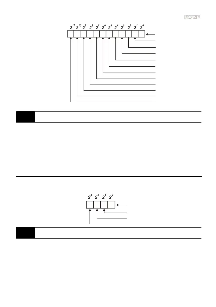
04.25 The Analog Input Used by PLC (NOT for VFD*E*C models)
Settings Read Only Factory display: 0
Display Bit0=1: AVI used by PLC
Bit1=1: ACI/AVI2 used by PLC
Bit2=1: AI1 used by PLC
Bit3=1: AI2 used by PLC
The equivalent 2-bit is used to display the status(used or not used) of each analog input. The
value for Pr.04.25 to display is the result after converting 2-bit binary into decimal value.
1
0
Weights
Bit
0=not used
1=used by PLC
AVI
ACI/AVI2
13
2
AI1 (optional)
AI2 (optional)
04.26 Display the Status of Multi-function Input Terminal
Settings Read Only Factory display: 63
Display Bit0: MI1 Status
Bit1: MI2 Status
Bit2: MI3 Status
Bit3: MI4 Status
Bit4: MI5 Status

Table of Contents

Questions and Answers:

Question and Answer IconNeed help?

Do you have a question about the Delta VFD-E and is the answer not in the manual?

Delta VFD-E Specifications

General IconGeneral
Protection FeaturesIP20
Enclosure RatingIP20
Overload Capacity150% for 60 seconds
Braking UnitBuilt-in
Control ModeV/F, Sensorless Vector
Protection FunctionsOvercurrent, Overvoltage, Undervoltage, Overheating, Short Circuit
Operating Temperature-10°C to +50°C
Analog Inputs2 (0-10V, 4-20mA)
Analog Outputs1 (0-10V)
Communication InterfaceRS-485
Output Voltage3-phase, equal to input voltage
Power Range0.4kW to 7.5 kW
Storage Temperature-20°C to +60°C
Humidity90% RH (non-condensing)
Cooling MethodFan cooled
Digital Outputs1 relay output

Related product manuals