Chapter 4 Parameters|
4-98 Revision Jan. 2009, 06EE, SW--PW V1.12/CTL V2.12
Display Bit0=1: MI1 used by PLC
Bit1=1: MI2 used by PLC
Bit2=1: MI3 used by PLC
Bit3=1: MI4 used by PLC
Bit4=1: MI5 used by PLC
Bit5=1: MI6 used by PLC
Bit6=1: MI7 used by PLC
Bit7=1: MI8 used by PLC
Bit8=1: MI9 used by PLC
Bit9=1: MI10 used by PLC
Bit10=1: MI11 used by PLC
Bit11=1: MI12 used by PLC
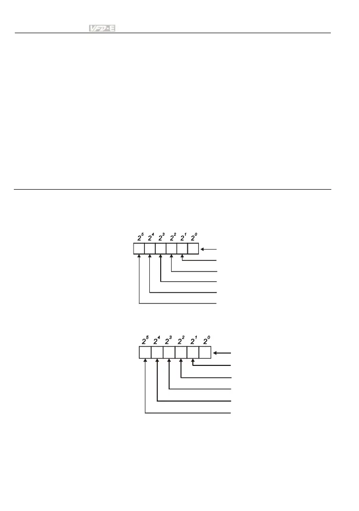
For standard AC motor drive (without extension card), the equivalent 6-bit is used to display
the status (used or not used) of each digital input. The value for Pr.04.24 to display is the
result after converting 6-bit binary into decimal value.
12345 0
0=not used
1=used by PLC
MI1
MI2
MI3
MI4
MI5
MI6
Weights
Bit
For example: when Pr.04.24 is set to 52 (decimal) = 110100 (binary) that indicates MI3, MI5
and MI6 are used by PLC.
01011 0
Weights
Bit
0=OFF
1=ON
MI1
MI2
MI3
MI4
MI5
MI6
When extension card is installed, the number of the digital input terminals will increase
according to the extension card. The maximum number of the digital input terminals is shown
as follows.