Chapter 4 Parameters|
Revision Jan. 2009, 06EE, SW--PW V1.12/CTL V2.12 4-171
Group 12: Analog Input/Output Parameters for Extension Card
Make sure that the extension card is installed on the AC motor drive correctly before using group 12
parameters. See Appendix B for details.
12.00
AI1 Function Selection
Factory Setting: 0
Settings 0 Disabled
1 Source of the 1st frequency
2 Source of the 2nd frequency
3 PID Set Point (PID enable)
4 Positive PID feedback
5 Negative PID feedback
12.01
AI1 Analog Signal Mode
Factory Setting: 1
Settings 0 ACI2 analog current (0.0 ~ 20.0mA)
1 AVI3 analog voltage (0.0 ~ 10.0V)
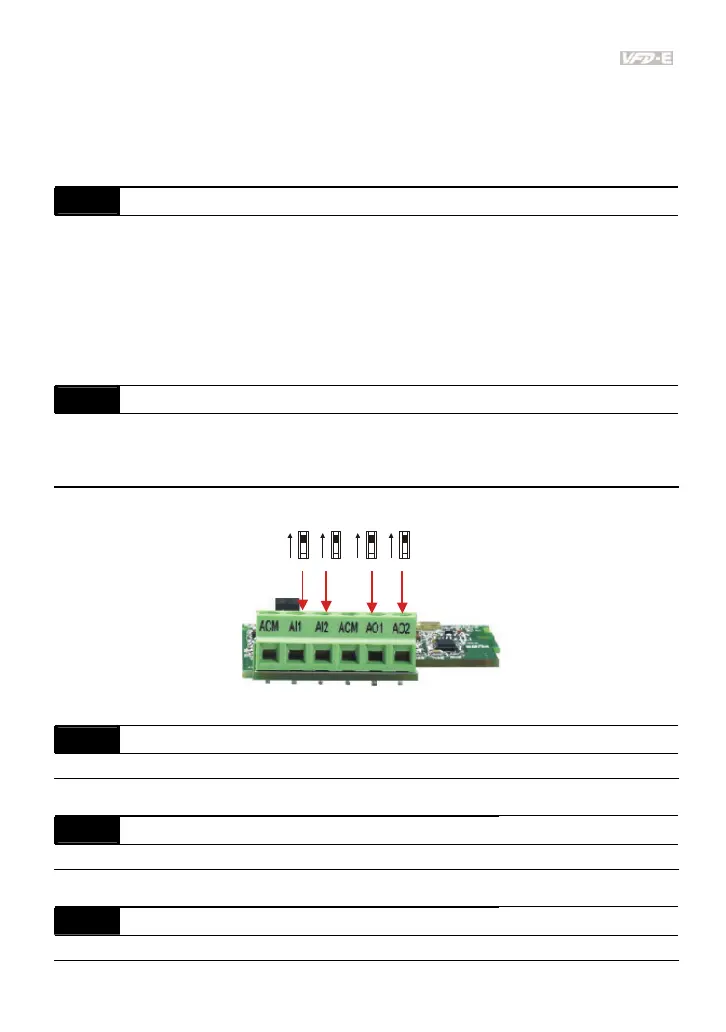
Besides parameters settings, the voltage/current mode should be used with the switch.
AVI3
ACI2
AVI4
ACI3
AVO1
ACO1
AVO2
ACO2
12.02 Min. AVI3 Input Voltage Unit: 0.1
Settings 0.0 to 10.0V Factory Setting: 0.0
12.03 Min. AVI3 Scale Percentage Unit: 0.1
Settings 0.0 to 100.0% Factory Setting: 0.0
12.04 Max. AVI3 Input Voltage Unit: 0.1
Settings 0.0 to 10.0V Factory Setting: 10.0