EasyManuals Logo

Delta VFD-E User Manual

Delta VFD-E
395 pages
To Next Page IconTo Next Page
To Previous Page IconTo Previous Page
Page #298 background imageLoading...
Page #298 background image
Appendix B Accessories|
Revision Jan. 2009, 06EE, SW--PW V1.12/CTL V2.12 B-29
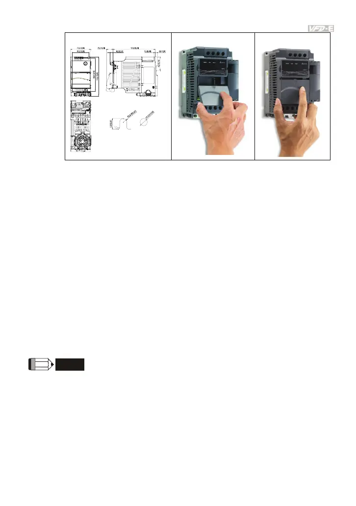
Dimensions
UNIT: mm(inch)
STEP 1 STEP 2
B.10.1.4 Power Supply
No external power is needed. Power is supplied via RS-485 port that is connected to VFD-E.
An 8 pins RJ-45 cable, which is packed together with this communication module, is used to
connect the RS-485 port between VFD-E and this communication module for power. This
communication module will perform the function once it is connected. Refer to the following
paragraph for LED indications.
B.10.1.5 LEDs Display
1. SP: Green LED means in normal condition, Red LED means abnormal condition.
2. Module: Green blinking LED means no I/O data transmission, Green steady LED means
I/O data transmission OK.
Red LED blinking or steady LED means module communication is abnormal.
3. Network: Green LED means DeviceNet communication is normal, Red LED means
abnormal
NOTE
Refer to user manual for detail information--
Chapter 5 Troubleshooting
.

Table of Contents

Questions and Answers:

Question and Answer IconNeed help?

Do you have a question about the Delta VFD-E and is the answer not in the manual?

Delta VFD-E Specifications

General IconGeneral
Protection FeaturesIP20
Enclosure RatingIP20
Overload Capacity150% for 60 seconds
Braking UnitBuilt-in
Control ModeV/F, Sensorless Vector
Protection FunctionsOvercurrent, Overvoltage, Undervoltage, Overheating, Short Circuit
Operating Temperature-10°C to +50°C
Analog Inputs2 (0-10V, 4-20mA)
Analog Outputs1 (0-10V)
Communication InterfaceRS-485
Output Voltage3-phase, equal to input voltage
Power Range0.4kW to 7.5 kW
Storage Temperature-20°C to +60°C
Humidity90% RH (non-condensing)
Cooling MethodFan cooled
Digital Outputs1 relay output

Related product manuals