Chapter 4 Parameters|
Revision Jan. 2009, 06EE, SW--PW V1.12/CTL V2.12 4-75
Related parameters: Pr.03.00(Multi-function Output Relay (RA1, RB1, RC1)) and
Pr.03.01(Multi-function Output Terminal MO1)
-2Hz
4Hz
2Hz
OFF
OFF
ON
ON
OFF
ON
OFF
ON
OFF
OFF
ON
OFF
ON
ON
detection
range
Frequenc
master
frequency
desired
frequency
03.02/03.14
detection range
detection
range
DC brake time
during stop
Time
waiting time
for
frequency
run/stop
setting 2
master freq. attained
(output signal)
setting 9/23
desired freq. attained
setting 03 zero speed indication
setting 19 zero speed indication
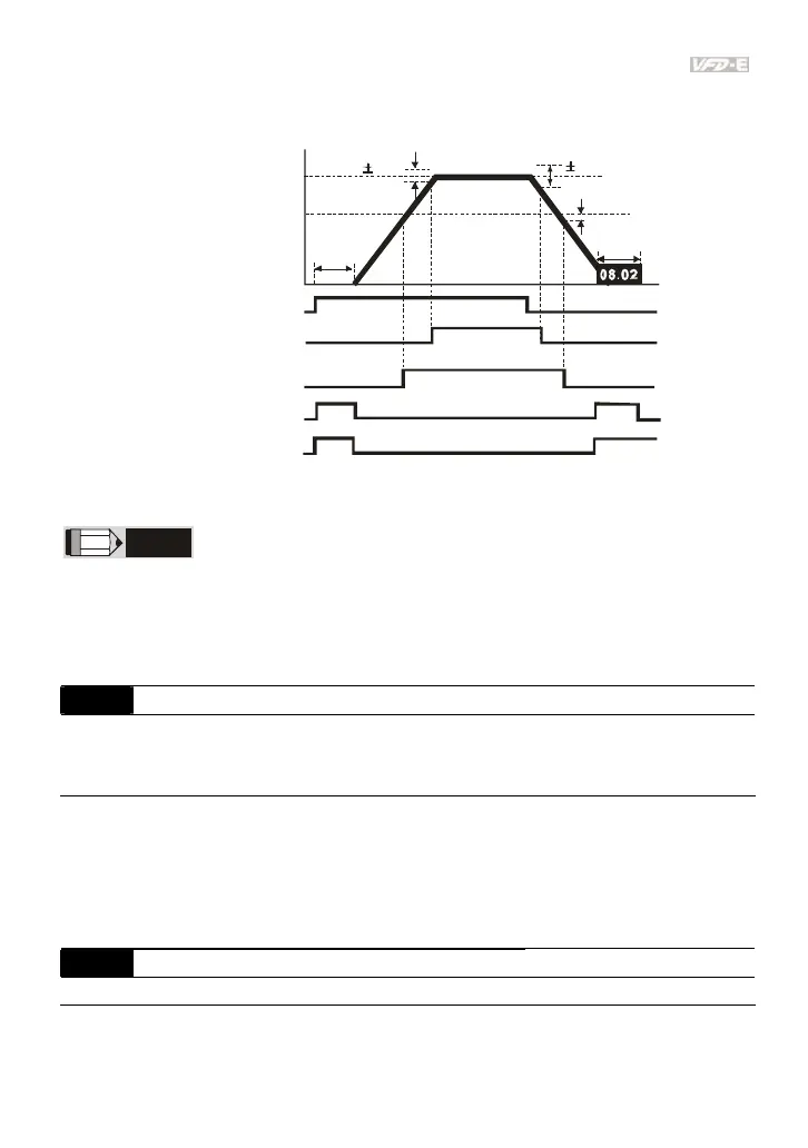
ou tp ut t iming ch art of m ul tip le funct io n termina ls(Pr.03.00/Pr.03.01)
when setting to frequency attained or zero speed indication
NOTE
When the output frequency reaches the setting frequency, the detection ranges for the multi-function
output terminals are:
±
2Hz (from OFF to ON) and
±
4Hz (from ON to OFF). The detection range for
the output frequency reaches the desired frequency is -2Hz.
03.03
Analog Output Signal (AFM)
Factory Setting: 0
Settings 0 Analog Frequency Meter (0 to Maximum Output Frequency)
1 Analog Current Meter (0 to 250% of rated AC motor drive current)
This parameter sets the function of the AFM output 0~+10VDC (ACM is common). Refer to
Pr.03.04 for applications.
Related parameters: Pr.01.00(Maximum Output Frequency (Fmax)) and Pr.03.04(Analog
Output Gain)
03.04 Analog Output Gain Unit: 1
Settings 1 to 200% Factory Setting: 100
This parameter sets the voltage range of the analog output signal AFM.