SIRIUS
®
TECHNICAL REFERENCE MANUAL
4.4.1.6. SYNC connector
Sync cable
The sync connectors are required when you want to use multiple SIRIUS® USB slices for the same
measurement. The signal that is transferred over this cable makes sure that the measurement data of
the different slices are perfectly synchronized to each other.
Sync connectors have 2 use-cases:
● SBOX: When you have an SBOX with GPS option, you can use the SBOX as a clock master. In this
case the SBOX will use the GPS signal to generate the synchronization signal for the attached
measurement modules: e.g. the SIRIUS-SBOXe has one sync connector at the front.
● SIRIUS® USB slices: When there are 2 connectors it's easy to chain several SIRIUS® chassis (or
DEWE-43, DS-CAN2, etc.) together.
Note that there is no distinction between the IN and OUT – it does not matter which connector
you use.
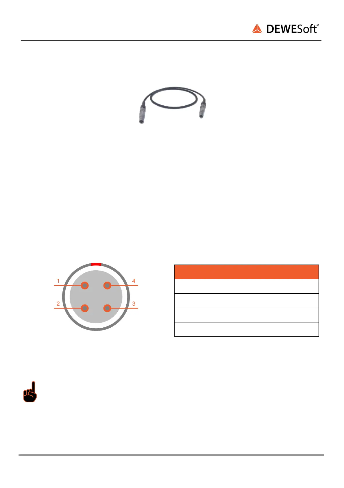
Interface connector: EEG.00.304.CLL
Mating connector: FGG.00.304.CLAD27Z
Important
When IRIG-synchronisation is used, the IRIG differential signals are on pins 1, 2.
When Clock / Trigger is used, the signals are on pins 1, 2.
When PPS-GPS synchronization is used, the PPS signal is on pin 3.
SIRIUS
®
V20-1 49 / 336