D-Show Guide142
Unavailable Plug-Ins
When a plug-in cannot be used because of insufficient DSP re-
sources, because it is disabled, or because it is not installed on
the system, a warning icon is shown in front of the affected
plug-in. The plug-in icon is greyed out, and the rack slot
Power switch displays a yellow switch LED.
For more information, see “Installing and Authorizing
Plug-Ins” on page 137.
Inactive Plug-Ins
When a plug-in has been manually made inactive, the plug-in
icon is greyed out. Plug-Ins can be made inactive manually,
letting you retain their assignment and settings in the rack
while freeing up their DSP resources for other tasks.
For more information, see “Active and Inactive Plug-Ins” on
page 144.
Rack Slots
Each rack provides 25 plug-in slots. You can assign any in-
stalled plug-in to any available rack slot.
Each rack slot provides the following controls to select and
manage plug-ins:
Power (Config Mode Only)
Power turns the rack slot on or off. When off, the plug-in con-
sumes no DSP.
In/Out (bypass)
The In/Out switch takes the rack slot in or out of circuit (by-
passes the slot and any plug-in assigned to it).
Input
The Input pop-up menu determines plug-in input (source).
Use this menu to designate the plug-in as a channel insert or
a bus processor by choosing from the Inserts or Bus
sub-menus. For more information, see “Routing Plug-Ins” on
page 144.
Once a plug-in has been routed, its input source is displayed
in the Input area of each rack slot, as follows:
• If the plug-in is being used as an insert, the channel or
bus name and number is shown, for example, Kick (Ch 1)
or Aux (1–2). The Channel Insert/Bus Output selector au-
tomatically switches to Channel Insert mode, showing
the insert point occupied by the plug-in.
• If the plug-in is on a bus, the selected bus source is shown
in the Input selector, for example, Aux 1 or Grp 1. The
Channel Insert/Bus Output selector can be used to assign
the output routing of the plug-in to a channel or bus.
Channel Insert or Bus Output
The Channel Insert/Bus Output pop-up menu displays differ-
ent choices depending on whether the plug-in is being used as
a channel insert, or as a bus processor, as follows:
• If the plug-in is being used as a channel insert, the Chan-
nel Insert selector shows the four insert points on that
channel (1–4). The letter “I” is shown before the insert
number (for example, I–1 indicates the current plug-in is
inserted into the first insert position on its channel).
•If the plug-in is being used as a bus processor, the menu
becomes the Output selector used to select the destina-
tion for plug-in output.
Plug-In Selector
The Plug-In selector displays a list of available plug-ins to load
into that rack slot. Plug-Ins are arranged by process type (such
as EQ, Dynamics, and Delay). For more information, see “As-
signing and Routing Plug-Ins” on page 143.
Indication of an unavailable plug-in
Indication of an inactive plug-in
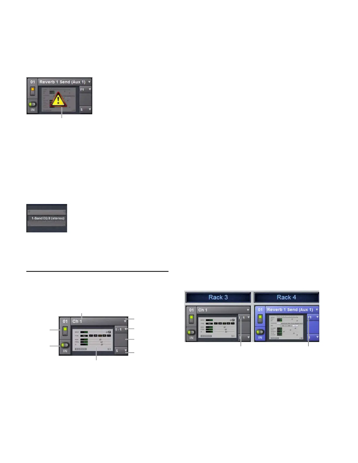
A rack slot and its controls, with an assigned plug-in shown
Unavailable plug-in
In/Out
Power
Channel Insert
Snapshots
Input (source)
Plug-In
or Output
Assigned plug-in
Current routing assignment
selector
A mono plug-in inserted on a channel (at left) and a stereo plug-in
assigned as a bus processor (at right)
Channel Insert
Bus Output