Chapter 19: Plug-Ins 141
Zoom View (Plug-In View Mode)
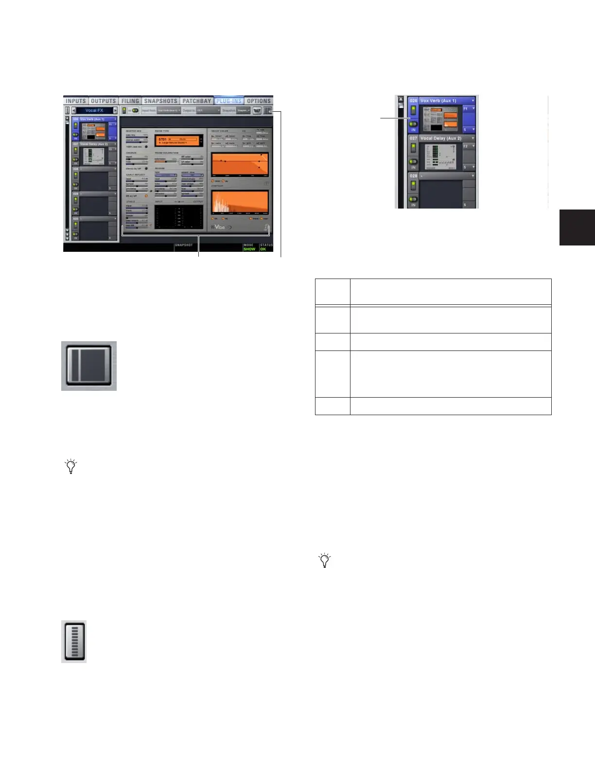
In Zoom view, a single rack remains on-screen to the left, and
the rest of the screen displays the targeted plug-in.
To toggle Full or Zoom view modes:
■ Press the Plug-Ins switch (in the View Modes section), or
click the View toggle switch (upper right corner of the rack).
– or –
■ Double-click a plug-in icon in any rack view to open that
plug-in window in Zoom view.
Mini-View Mode
Mini-view mode is an option available in Full and Zoom
modes in which the rack slot displays are minimized and
plug-in icons are hidden, to let you see more of the racks at
one time. You can bypass, route, and work with plug-in snap-
shot controls in Mini-view mode.
To toggle mini-view on or off:
1 Click the Mini-view icon (upper left corner of the rack view).
Identifying Rack Slots
The racks indicate which plug-in is currently targeted by high-
lighting its rack slot controls in blue.
Within each rack slot, color outlines appear around each
plug-in to indicate the type of plug-in currently targeted on
the control surface. The following colors are used:
Display of Unavailable or Inactive Plug-Ins
It is possible for a plug-in to be displayed in a rack slot but be
unavailable for channel and bus processing. This can occur in
any of the following circumstances:
• There are not enough DSP resources available for the
plug-in.
• The assigned plug-in is part of the show file but is not in-
stalled on the current system.
•The plug-in has been disabled manually.
Zoom view, with a plug-in window open on-screen
Zoom/Full view toggle
D-Show provides other ways to jump to a plug-in view. For
more information, see ““Jump To” Plug-Ins” on page 146.
Mini-view
Plug-In display
View Toggle
Highlighted rack slot indicating targeted plug-in
Outline Color Coding of Rack Slots
Color
Outline
Indication
Yellow A Dynamics plug-in, mapped to the ACS Dynamics sec-
tion
Green An EQ plug-in, mapped to the ACS EQ section
Red The plug-in is mapped to more than one control surface
section. For example, an EQ plug-in that is currently
mapped to both the ACS EQ controls and the Assignable
Output Encoders.
Blue A plug-in mapped to the Assignable Output Encoders
Place the cursor over the Tool Tips icon to see an expla-
nation of why the plug-in is not available. To view DSP
resource allocation, see “DSPs Available for Plug-Ins” on
page 42.
Targeted plug-in
(rack slot
highlighted in
blue)