D-Show Guide56
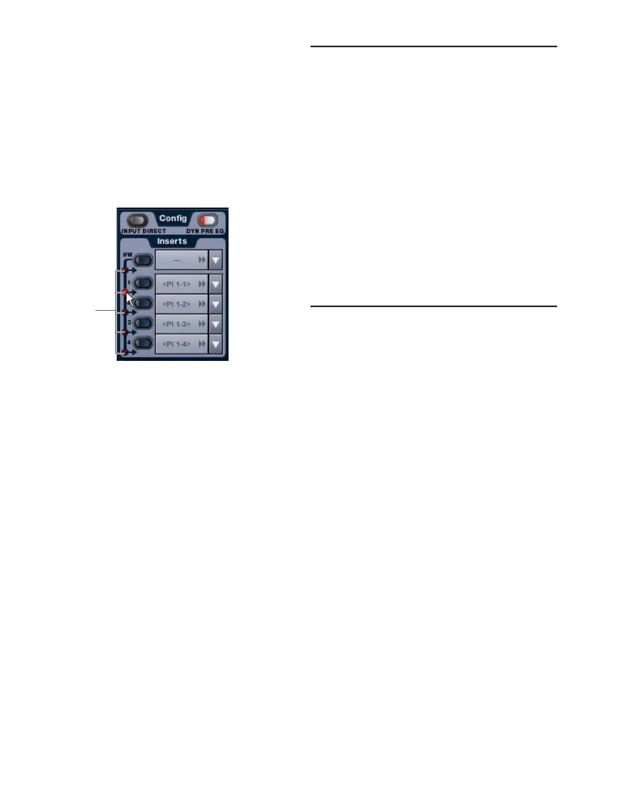
Setting the Hardware Insert Location
You can choose the location of the hardware insert in the sig-
nal path, relative to the four plug-in inserts, for each channel.
A hardware insert does not need to be currently assigned to do
this.
To set the hardware insert location:
1 Go to the Inputs page and target the channel where you
want to set the hardware insert location.
2 In the Inserts section of the Inputs page, click the hardware
insert indicator so that it lights red.
Activating and Bypassing Inserts
After hardware and plug-in inserts are assigned, they can be
activated and bypassed from the from the ACS section or the
corresponding Input page controls.
Hardware inserts can be also be activated and bypassed di-
rectly from Input Channels and FX Returns.
To activate or bypass a channel’s plug-in or hardware insert from
the ACS section:
1 Target the channel by pressing its Select switch.
2 Press any of the Plug-In switches or the Hardware switch to
activate or bypass the corresponding Insert. The switch lights
when the insert is activated.
To activate or bypass a hardware insert from an Input Channel or
FX Return:
■ Press the Insert In switch on the channel. The switch lights
when the insert is in-circuit.
Using Input Direct
Input Direct mode lets you completely bypass the built-in dy-
namics and EQ processing, and all inserts on Input Channels
and FX Returns. This mode routes the input signal directly
from the Top of Channel pickoff to the channel fader.
Input Channels Input Direct bypasses the HPF, built-in dynam-
ics and EQ, plug-in inserts, and the hardware insert point on
Input Channels.
FX Returns Input Direct bypasses the built-in EQ, plug-in in-
serts, and the hardware insert point on FX Returns.
To bypass all processing on an input channel:
1 Target the channel by pressing its Select switch.
2 Press the Input Direct switch in the Channel Config section
of the ACS. The switch flashes to indicate Input Direct mode is
active on the targeted channel.
Adjusting Input Controls
Input Gain
Input Gain is adjustable from the rotary encoders on each In-
put Channel and FX Return. Mic inputs have a gain range
from +10 dB to +60 dB. Analog line inputs and digital inputs
have a gain range from –20 dB to +18 dB.
Gain Guess Feature
An automated Gain Guess function can be used to set a nom-
inal level for a channel based on its incoming signal. When
you press and hold the rotary encoder assigned to control gain
(either the bottom row of input encoders or the Input Gain
encoder in the ACS section), the system samples incoming sig-
nals and automatically sets the channel gain and pad for a
0 dB reference when the encoder is released.
Gain Indicators
When Gain is displayed on the lower row of input encoders,
the encoder’s indicator LED lights to indicate that the gain is
set to the default value (+10 dB for analog inputs, and 0 dB for
digital inputs). Gain change is indicated by the encoder ring
LEDs, and gain value is shown in the channel display.
Setting a hardware insert location in the Inputs page
Click to set
HW Insert
location