Chapter 7: Inputs and Input Routing 57
Setting Input Gain
Gain can be controlled from individual channel strips or from
the ACS section.
To adjust input gain for a channel:
1 Do one of the following:
• In the Encoder Assignment section, press the Gain switch
to assign gain control to the bottom row of rotary encod-
ers.
– or –
•Target the channel by pressing its Select switch. Gain
control for the channel is assigned to the Input Gain ro-
tary encoder in the ACS section.
2 Adjust the gain by turning the assigned rotary encoder.
To adjust input gain using the Gain Guess feature:
1 Press and hold the assigned rotary encoder while the chan-
nel is receiving input signal. The LED flashes to indicate level
sampling.
2 Release the rotary encoder to the current gain guess.
Setting Right Offset on Stereo Channels
On stereo Input Channels and FX Returns, the Gain control
affects both the left and right channels. The Right Offset fea-
ture lets you offset the gain of the right channel relative to the
left channel by –20 dB to +20 dB, within the overall gain lim-
its.
To adjust channel gain offset for a stereo channel:
1 Do one of the following:
• In the Encoder Assignment section, press the Right Offset
switch to assign offset control to the bottom row of ro-
tary encoders.
– or –
•Target the channel by pressing its Select switch, then
press the Right Offset switch in the ACS Input section.
Channel Gain Offset is assigned to the Input Gain rotary
encoder in the ACS section.
2 Adjust the right channel gain offset by turning the assigned
rotary encoder.
Stereo Level Offset Indication
With stereo channels, if the difference in signal level between
the left and right channels is 12 dB or greater, the Stereo LED
below the channel meter flashes.
Pan
Pan adjusts channel pan (for mono Input Channels) and ste-
reo balance (for stereo Input Channels and FX Returns), allow-
ing you to control panning of signal to Groups or to Mains.
To adjust channel pan/balance:
1 Do one of the following:
• In the Encoder Assignment section, press the Pan switch
to assign pan/balance control to the bottom row of ro-
tary encoders.
– or –
•Target the channel by pressing its Select switch. Pan/bal-
ance control is assigned to the Width/Pan rotary encoder
in the ACS section.
2 Adjust the channel pan/balance by turning the assigned ro-
tary encoder.
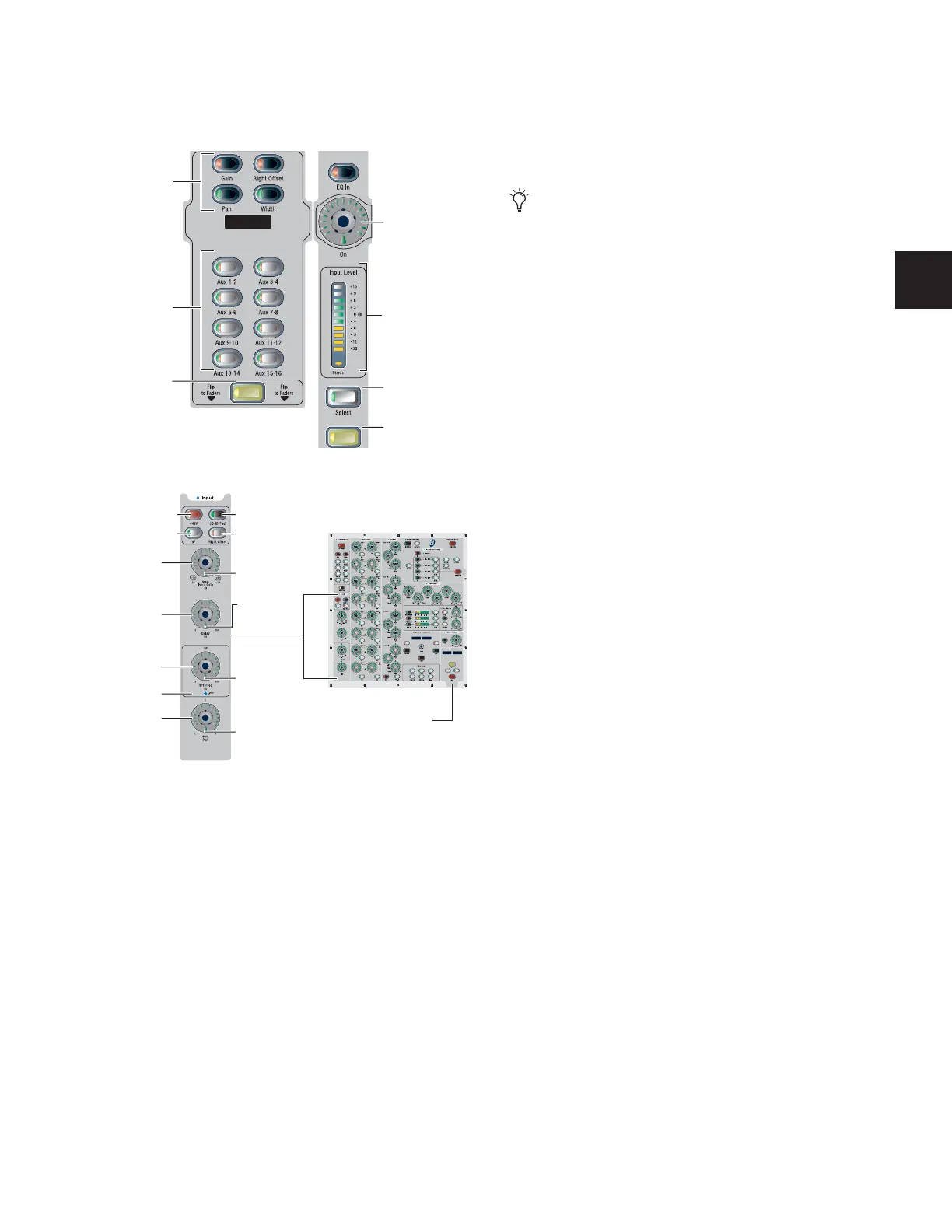
Input controls on input channel strips
Input controls and their location in the ACS
Input meter
Select
Solo
Encoder 2
Aux Assign
Flip
Encoder 2
Assign
switches
KICKKICK
KICK KICK
HPF
Pan
HPF Freq
Delay
Input Gain
Polarity
+48V 20
dB Pad
Right Offset
(Width)
ACS
Selected Channel
Solo and Mute
Available
Default LED
In/Out LED
Default
(Center) LED
In/Out LED
When gain control is assigned to Encoder 2, you can press
encoders on multiple channels simultaneously to use Gain
Guess on each channel.