Chapter 13: Metering 95
Chapter 13: Metering
D-Show provides signal metering on the control surface chan-
nels and meter bridge, and on-screen.
Channel Meters
All control surface channel meters have on-screen equivalents
that appear in both the targeted channel controls and just
above the faders in the channel overview.
Meter ballistics and clip margin can be set for channel meters.
For more information, see “Metering Options” on page 99.
Input Channels and FX Returns
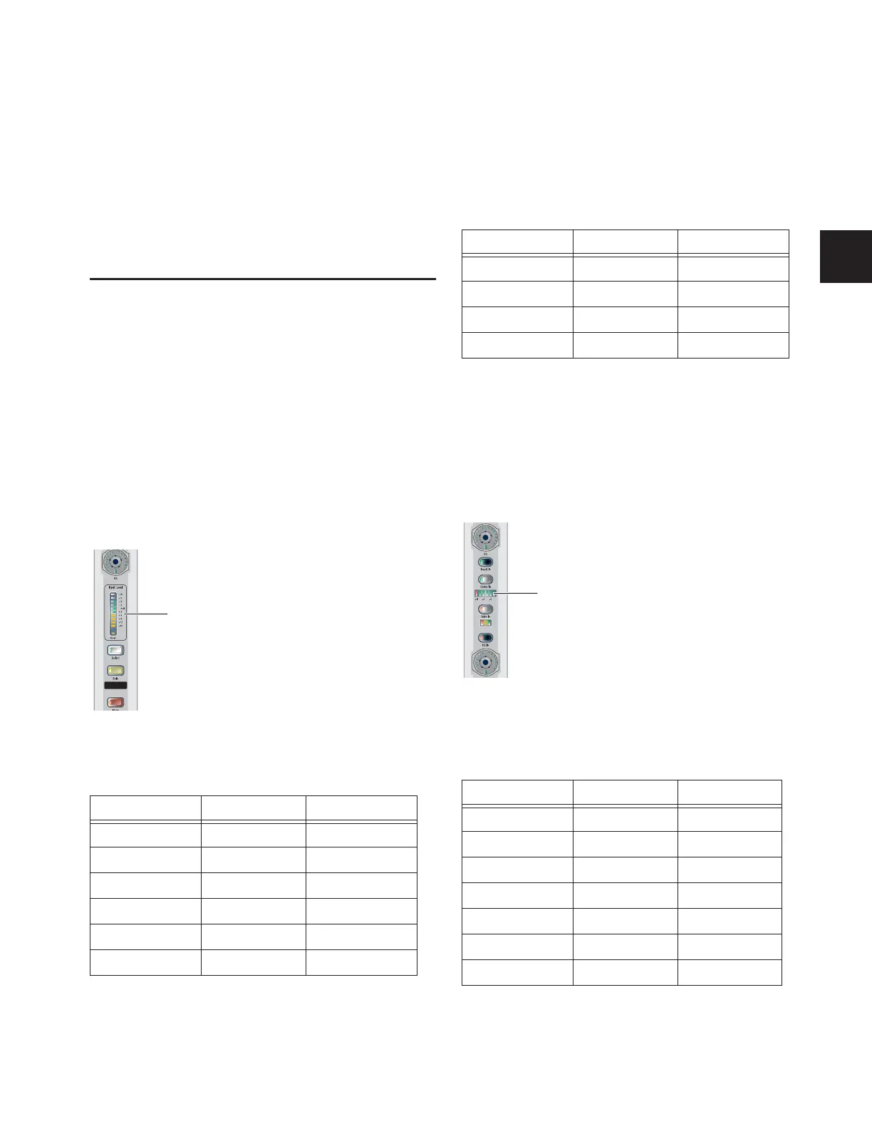
Input Level Meters
Each Input Channel and FX Return channel strip has a 10-seg-
ment bi-color Input Level meter.
The 10 bi-color LEDs on the Input Level meters show input
levels from bottom to top, according to the following scale:
Dynamics Gain Reduction Meters
Each Input Channel and FX Return channel strip has two gain
reduction meters that show the amount of gain reduction ap-
plied by the built-in Compressor/Limiter (6-segment meter) or
Expander/Gate (3-segment meter).
Compressor/Limiter Meter
The 6 LEDs on the Compressor/Limiter meter show gain re-
duction levels from right to left, according to the following
scale:
Channel Input Level meter
Channel Input Level meter scale
LED Level Color
1 (top) 15 dB Yellow
29 dB Yellow
36 dB Yellow
43 dB Yellow
50 dB Green
6 –3 dB Green
Channel Input Level
meter
7 –6 dB Green
8 –9 dB Green
9 –12 dB Green
10 (bottom) –30 dB Green
Channel Compressor/Limiter meter
Channel Compressor/Limiter gain reduction meter scale
LED Gain Reduction Color
(none) 0 dB (none)
1 (right) 3 dB Green
26 dB Green
39 dB Green
4 12 dB Green
5 15 dB Green
6 (left) 21 dB Red
Channel Input Level meter scale
LED Level Color
Channel Compressor/Limiter
gain reduction meter