Chapter 2: Configuring and Connecting D-Show 7
Chapter 2: Configuring and Connecting D-Show
The D-Show Main Unit and Sidecar can be placed in any or-
der, and the input channel strip order configured accordingly.
You can then bank input channels across the available input
channel strips.
Determining Control Surface Layout
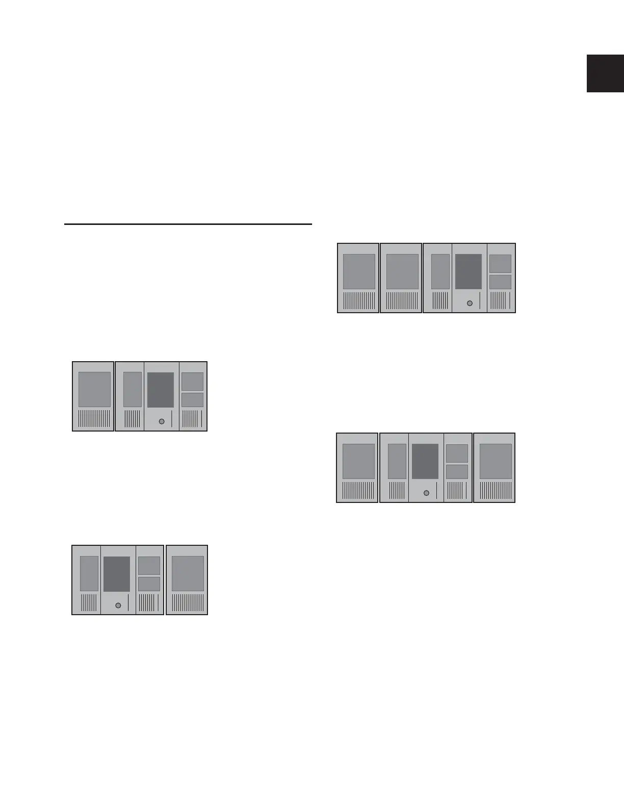
Standard System Layout
On a standard D-Show system (one Main Unit and a single
Sidecar on the left), D-Show input channel strips 1–16 appear
by default on the Sidecar module, and channel strips 17–24
appear on the Main Unit.
You can place the Sidecar on the other side of the Main Unit,
and customize the order of input channel strips by changing
the Bus IDs of the units. See “Setting Control Surface Bus IDs”
on page 8.
Expanded System Layout
On expanded D-Show systems, by default, input channel
strips 1–16 appear on the leftmost Sidecar and progress to the
right.
You can place Sidecars on either side of the Main Unit, and
customize the order of input channel strips by changing the
Bus IDs of the units. See “Setting Control Surface Bus IDs” on
page 8.
Input channel strip numbering on a standard system
Alternative input channel strip numbering on a standard system
Main Unit Sidecar
Strips 1–16 17–24
(Bus ID 1) (Bus ID 2)
Main Unit Sidecar
9–24
(Bus ID 2)(Bus ID 1)
Strips 1–8
Input channel strip numbering on an expanded system
Alternative input channel numbering on an expanded system
Main Unit Sidecar 1
Strips 1–16 33–40
Sidecar 2
17–32
(Bus ID 1) (Bus ID 2) (Bus ID 3)
Main Unit Sidecar 1
Strips 1– 6
Sidecar 2
17–24
(Bus ID 1) (Bus ID 3)(Bus ID 2)
25–40