CYLINDER-TO-WATER JACKET LEAKAGE TEST
WARNING: USE EXTREME CAUTION WHEN THE
ENGINE IS OPERATING WITH COOLANT PRES-
SURE CAP REMOVED.
VISUAL TEST METHOD
With the engine cool, remove the coolant pressure
cap. Start the engine and allow it to warm up until
thermostat opens.
If a large combustion/compression pressure leak
exists, bubbles will be visible in the coolant.
COOLING SYSTEM TESTER METHOD
WARNING: WITH COOLING SYSTEM TESTER IN
PLACE, PRESSURE WILL BUILD UP FAST. EXCES-
SIVE PRESSURE BUILT UP, BY CONTINUOUS
ENGINE OPERATION, MUST BE RELEASED TO A
SAFE PRESSURE POINT. NEVER PERMIT PRES-
SURE TO EXCEED 138 kPa (20 psi).
Install Cooling System Tester 7700 or equivalent to
pressure cap neck. Start the engine and observe the
tester’s pressure gauge. If gauge pulsates with every
power stroke of a cylinder a combustion pressure
leak is evident.
CHEMICAL TEST METHOD
Combustion leaks into the cooling system can also
be checked by using Bloc-Chek Kit C-3685-A or
equivalent. Perform test following the procedures
supplied with the tool kit.
REMOVAL
(1) Perform fuel pressure release procedure before
attempting any repairs. (Refer to 14 - FUEL SYS-
TEM/FUEL DELIVERY - STANDARD PROCE-
DURE)
(2) Disconnect negative cable from remote jumper
terminal.
(3) Drain cooling system (Refer to 7 - COOLING/
ENGINE - STANDARD PROCEDURE) and remove
accessory drive belts (Refer to 7 - COOLING/ACCES-
SORY DRIVE/DRIVE BELTS - REMOVAL).
(4) Remove the vibration dampner (Refer to 9 -
ENGINE/ENGINE BLOCK/VIBRATION DAMPER -
REMOVAL).
(5) Remove upper and lower intake manifolds(Re-
fer to 9 - ENGINE/MANIFOLDS/INTAKE MANI-
FOLD - REMOVAL).
(6) Remove cylinder head cover and timing chain
cover. (Refer to 9 - ENGINE/CYLINDER HEAD/CYL-
INDER HEAD COVER(S) - REMOVAL) (Refer to 9 -
ENGINE/VALVE TIMING/TIMING BELT / CHAIN
COVER(S) - REMOVAL)
(7) Remove water outlet connector (Fig. 12). (Refer
to 7 - COOLING/ENGINE/COOLANT OUTLET
HOUSING - REMOVAL)
(8) Rotate crankshaft until crankshaft sprocket
timing mark aligns with timing mark on oil pump
housing.
(9) Remove primary timing chain. (Refer to 9 -
ENGINE/VALVE TIMING/TIMING BELT/CHAIN
AND SPROCKETS - REMOVAL)
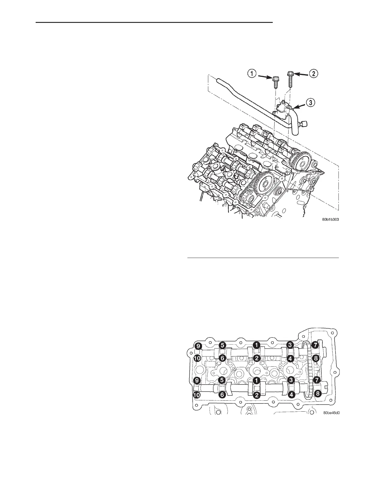
(10) Remove camshaft bearing caps gradually in
REVERSE sequence of installation (10–1) (Fig. 13).
(11) Remove camshafts and valvetrain components
from cylinder head (Fig. 14). Note component loca-
tions for re-installation in original locations.
Fig. 12 WATER OUTLET CONNECTOR
1 - BOLT (2)
2 - BOLT (2)
3 - WATER OUTLET CONNECTOR
Fig. 13 CAMSHAFT BEARING CAPS
LH ENGINE 2.7L 9 - 25
CYLINDER HEAD (Continued)