(7) Remove electrical connector harness bracket.
(8) Disconnect oxygen sensor electrical connector
and remove sensor from manifold.
(9) Remove heat shield attaching bolts and remove
heat shield (Fig. 132).
(10) Remove exhaust manifold attaching bolts (Fig.
132).
(11) Remove exhaust manifold and gasket (Fig.
132).
INSPECTION
(1) Inspect exhaust manifolds for damage or
cracks.
(2) Check manifold flatness.
(3) Inspect the exhaust manifold gasket for obvi-
ous discoloration or distortion.
(4) Check distortion of the cylinder head mounting
surface with a straightedge and thickness gauge.
INSTALLATION
(1) Install the exhaust manifold and gasket.
Tighten bolts starting at the center working outward
to 23 N·m (200 in. lbs.) (Fig. 132).
(2) Install heat shields and tighten bolts to 12 N·m
(105 in. lbs.) (Fig. 132).
(3) Install oxygen sensor to manifold and connect
electrical connector.
(4) Attach electrical connector bracket to brace.
(5) Install a new V-Band clamp and tighten to 11
N·m (100 In. lbs.).
(6) Raise vehicle on hoist.
(7) Install and/or tighten nut attaching converter
pipe support to transaxle mount to 47 N·m (35 ft.
lbs.).
(8) Install the exhaust system. (Refer to 11 -
EXHAUST SYSTEM - INSTALLATION)
(9) Lower vehicle and connect negative cable.
VALVE TIMING
DESCRIPTION
The timing drive system (Fig. 133) has been
designed to provide quiet performance and reliability
to support a NON free-wheeling engine.
The timing drive components include a crankshaft
sprocket, camshaft sprockets, tensioner pulley,
hydraulic tensioner and a timing belt. The water
pump is driven by the back side of the timing belt.
The right and left camshaft sprockets are not inter-
changeable because of the cam sensor pick-up wheel
on the left sprocket.
STANDARD PROCEDURE - VALVE TIMING
VERIFICATION
(1) Refer to Camshaft Sprocket Removal procedure
for verification of valve timing (Refer to 9 - ENGINE/
VALVE TIMING/TIMING BELT/CHAIN AND
SPROCKETS - REMOVAL)
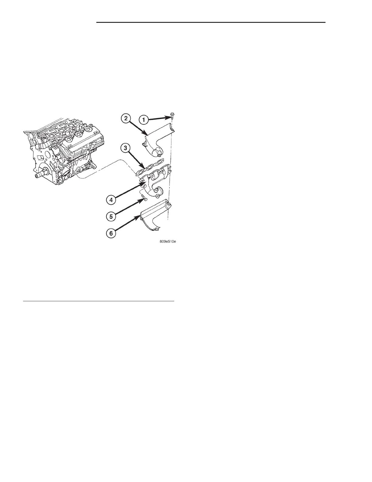
Fig. 132 EXHAUST MANIFOLD
1 - BOLT - HEAT SHIELD
2 - HEAT SHIELD
3 - GASKET
4 - EXHAUST MANIFOLD
5 - BOLT - EXHAUST MANIFOLD
6 - HEAT SHIELD
9 - 166 ENGINE 3.5L LH
EXHAUST MANIFOLD - LEFT (Continued)