DISASSEMBLY
NOTE: If the valve body is being reconditioned or
replaced, it is necessary to perform the Quick Learn
Procedure using the DRBIIIT Scan Tool (Refer to 8 -
ELECTRICAL/ELECTRONIC CONTROL MODULES/
POWERTRAIN CONTROL MODULE - STANDARD
PROCEDURE)
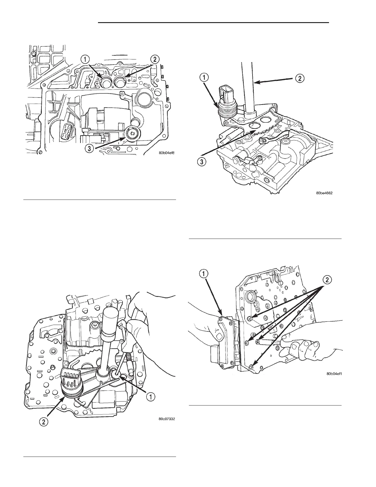
(1) Remove manual shaft seal.
(2) Remove manual shaft screw (Fig. 416).
(3) Remove Transmission Range Sensor (TRS) and
manual shaft (Fig. 417).
(4) Remove Solenoid/Pressure Switch Assembly
from valve body (Fig. 418).
Fig. 415 Overdrive, Underdrive and Low/Reverse
Accumulator Location
1 - OVERDRIVE ACCUMULATOR LOCATION
2 - UNDERDRIVE ACCUMULATOR LOCATION
3 - LOW/REVERSE ACCUMULATOR
Fig. 416 Manual Shaft Retaining Screw
1 - SCREW
2 - TRS
Fig. 417 Manual Shaft/Rooster Comb and
Transmission Range Sensor
1 - TRANSMISSION RANGE SENSOR
2 - MANUAL SHAFT
3 - ROOSTER COMB
Fig. 418 Solenoid Retaining Screws
1 - SOLENOID/PRESSURE SWITCH ASSEMBLY
2 - RETAINING SCREWS
21 - 158 TRANSAXLE LH
VALVE BODY (Continued)