(7) Loosen upper fastener at throttle body support
bracket.
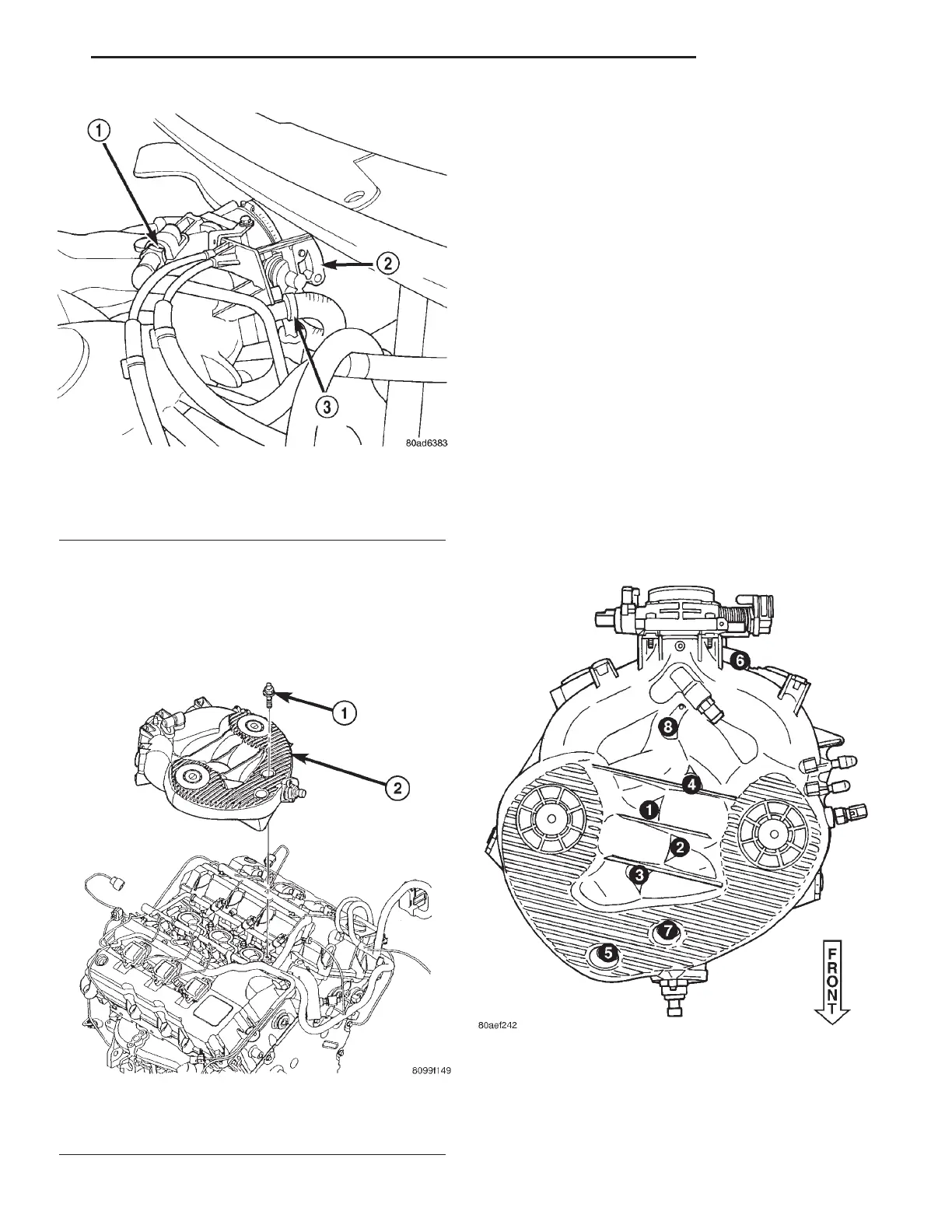
(8) Remove manifold attaching bolts (Fig. 107).
(9) Remove upper manifold (Fig. 106).
(10) Inspect manifold (Refer to 9 - ENGINE/MAN-
IFOLDS/INTAKE MANIFOLD - INSPECTION).
INSPECTION
Check manifold for:
• Damage and cracks
• Gasket surface damage or warpage
• Damaged or clogged EGR ports
If the manifold exihibits any damaged or warped
conditions, replace the manifold. Clean EGR ports as
neccessary.
If a vacuum port is damaged, a repair procedure
can be performed (Refer to 9 - ENGINE/MANI-
FOLDS/INTAKE MANIFOLD - STANDARD PROCE-
DURE).
INSTALLATION
(1) Clean and inspect sealing surfaces. Gaskets
can be reused, if free of cuts or tears.
NOTE: Make sure fuel injectors and wiring har-
nesses are in correct position to not interfere with
upper manifold installation.
(2) Position upper manifold onto lower manifold
(Fig. 106).
(3) Install manifold attaching bolts and tighten in
sequence shown in (Fig. 107) to 12 N·m (105 in. lbs.).
(4) Tighten upper fastener at throttle body support
bracket.
(5) Connect speed control servo, PCV (Fig. 105),
brake booster, and vapor purge hoses.
Fig. 105 PCV VALVE
1 - PCV VALVE
2 - THROTTLE BODY
3 - EGR TUBE
Fig. 106 INTAKE MANIFOLD - UPPER
1 - BOLT
2 - INTAKE MANIFOLD - UPPER
Fig. 107 Upper Intake Manifold Tightening Sequence
LH ENGINE 2.7L 9 - 73
INTAKE MANIFOLD - UPPER (Continued)