INSTALLATION
(1) Verify o-ring is installed into position (Fig. 391)
.
(2) Install and tighten output speed sensor to 27
N·m (20 ft. lbs.) torque.
(3) Connect speed sensor connector (Fig. 390) .
(4) Connect battery negative cable.
TORQUE CONVERTER
DESCRIPTION
The torque converter is located in the bellhousing
area of the transaxle, between the engine and trans-
axle. The torque converter is a fluid coupling that
transmits torque from the engine drive plate to the
input shaft of the transaxle. The torque converter
consists of four main components (Fig. 392):
• Impeller
• Turbine
• Stator
• Converter Clutch assembly
OPERATION
The converter impeller (driving member), which is
integral to the converter housing and bolted to the
engine drive plate, rotates at engine speed. The con-
verter turbine (driven member), which reacts from
fluid pressure generated by the impeller, rotates and
turns the transmission input shaft.
Torque is transmitted by fluid passing through
curved vanes in both the impeller and turbine. Since
the coupling is produced by transmission fluid, the
turbine can slip or turn slower than the impeller.
The stator contains a one-way overrunning clutch,
which free-wheels when the impeller and turbine are
rotating at the same speed. However, the stator stops
when speed reduction or torque increase take place.
When the stator stops, it changes the direction of the
fluid leaving the turbine vanes. This directs fluid
back into the impeller with greater force, resulting in
torque multiplication.
The torque converter clutch is hydraulically oper-
ated and controlled by the TCM. It consists of a pis-
ton and a frictional disc that form a direct
mechanical link between the impeller and turbine
when slippage is inefficient or unnecessary.
The torque converter hub drives the transmission
oil pump.
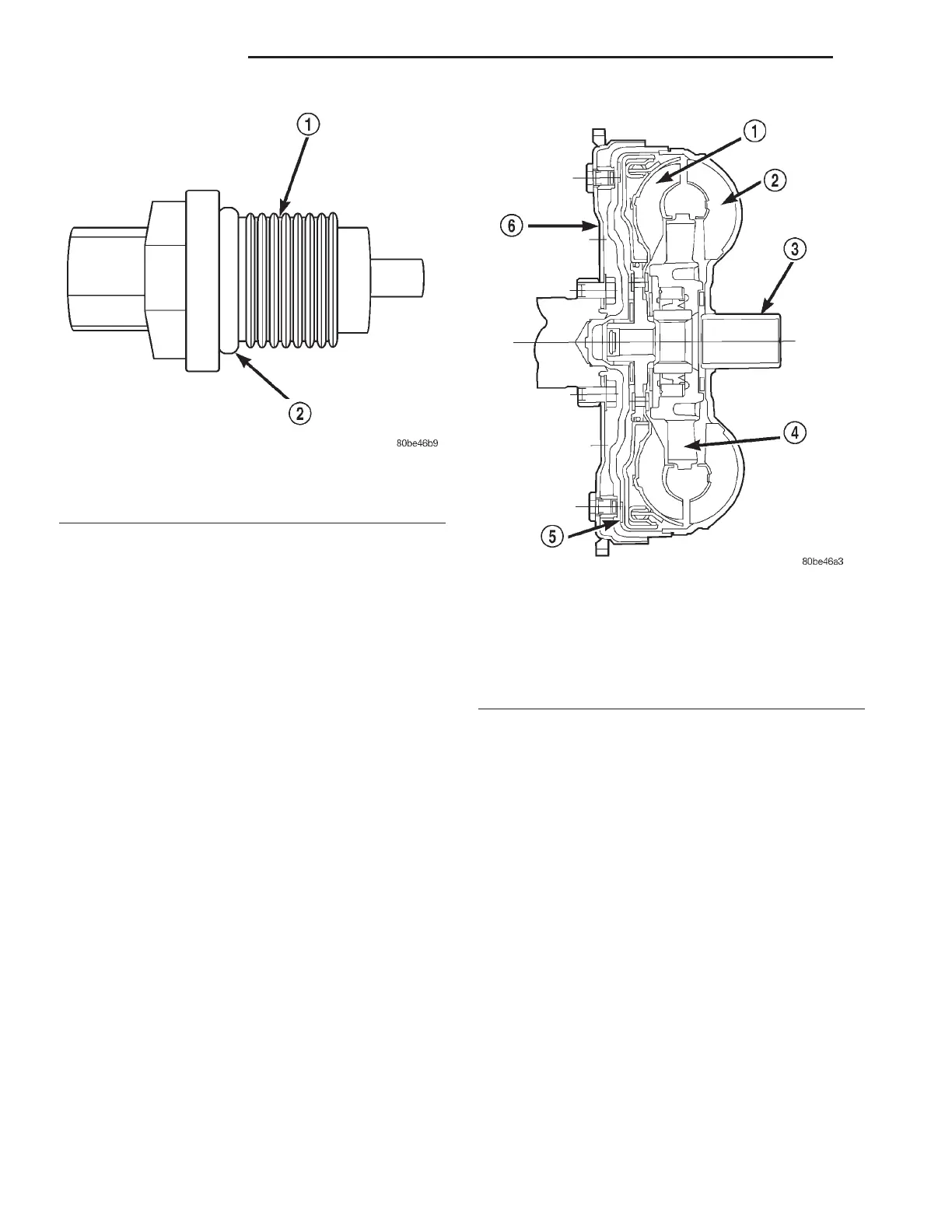
Fig. 391 O-Ring Location
1 - OUTPUT SPEED SENSOR
2 - O-RING
Fig. 392 Torque Converter Assembly
1 - TURBINE
2 - IMPELLER
3 - HUB
4-STATOR
5 - CONVERTER CLUTCH DISC
6 - DRIVE PLATE
21 - 148 TRANSAXLE LH
SPEED SENSOR - OUTPUT (Continued)