REMOVAL
(1) Remove cylinder head cover(s). (Refer to 9 -
ENGINE/CYLINDER HEAD/CYLINDER HEAD
COVER(S) - REMOVAL)
(2) Remove rocker arm(s). (Refer to 9 - ENGINE/
CYLINDER HEAD/ROCKER ARMS - REMOVAL)
CAUTION: If lash adjusters and rocker arms are to
be reused, always mark position for reassembly in
their original positions.
(3) Remove lash adjuster(s).
INSTALLATION
(1) Install hydraulic lash adjuster making sure
adjusters are at least partially full of oil. This can be
verified by little or no plunger travel when lash
adjuster is depressed.
(2) Install rocker arm(s) (Refer to 9 - ENGINE/
CYLINDER HEAD/ROCKER ARMS - INSTALLA-
TION) and cylinder head covers (Refer to 9 -
ENGINE/CYLINDER HEAD/CYLINDER HEAD
COVER(S) - INSTALLATION).
ROCKER ARMS
DESCRIPTION
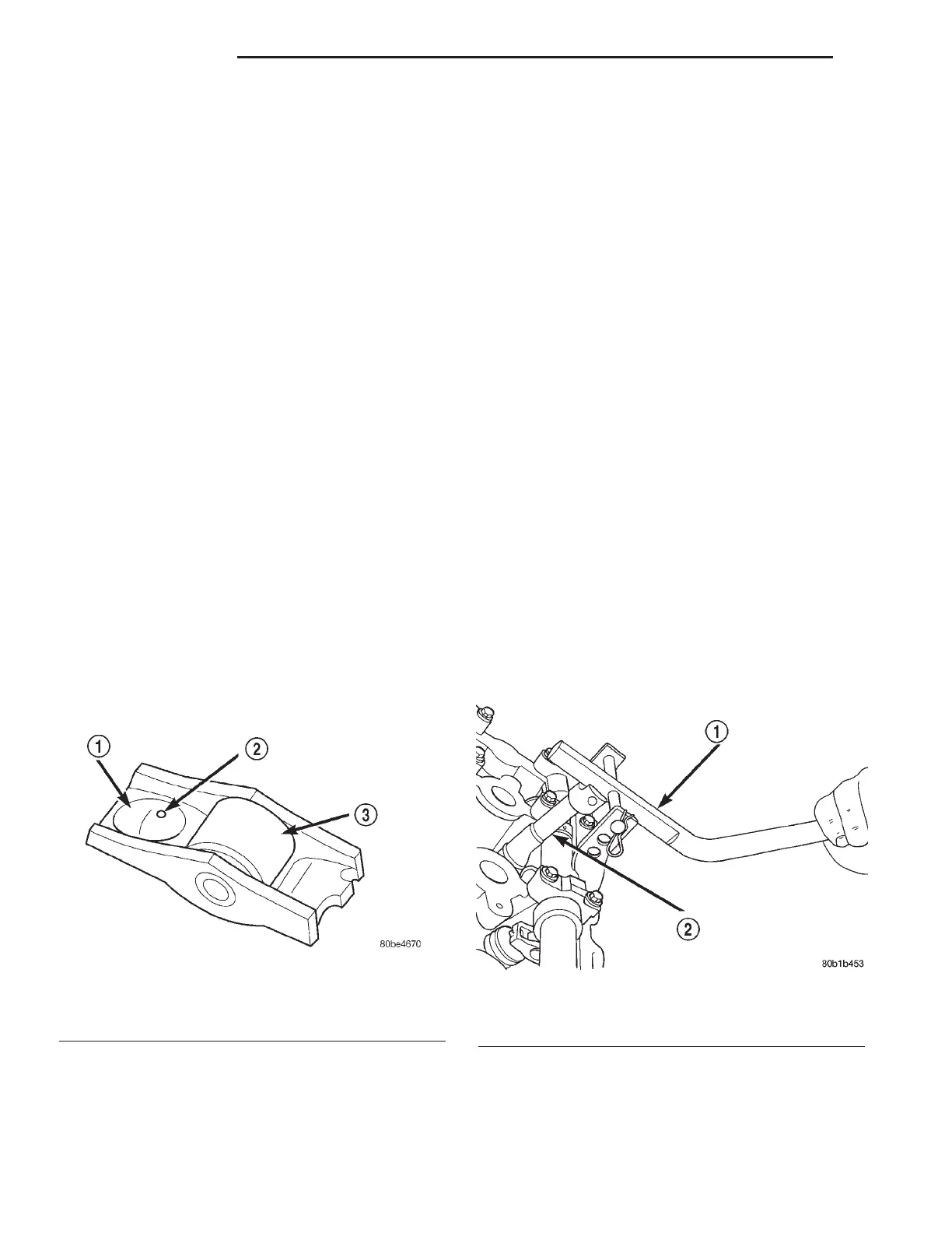
The rocker arms are composed of steel stampings
with an integral roller bearing (Fig. 39). The rocker
arms incorporate a 0.5 mm (0.0197 in.) oil hole in the
lash adjuster socket for roller/camshaft lobe lubrica-
tion (Fig. 39).
OPERATION
The rocker arm is the pivot point between the cam-
shaft lobe and the valve.
REMOVAL
(1) Remove cylinder head cover(s). (Refer to 9 -
ENGINE/CYLINDER HEAD/CYLINDER HEAD
COVER(S) - REMOVAL)
CAUTION: Always rotate engine by turning the
crankshaft. Failure to do so will result in valve
and/or piston damage.
(2) Rotate engine until the cam lobe is on its base
circle (heel), on the rocker arm being removed.
CAUTION: Depress valve spring only enough to
remove rocker arm.
(3) Using Special Tools 8215 and 8216 Adaptor,
depress valve spring only enough to release tension
on rocker arm (Fig. 40).
(4) Remove rocker arm from cylinder head.
CAUTION: If rocker arms are to be reused, identify
position of rocker arms for reassembly in their orig-
inal positions.
(5) Repeat procedure for each rocker arm removed.
(6) Inspect the rocker arm for wear or damage.
(Refer to 9 - ENGINE/CYLINDER HEAD/ROCKER
ARMS - INSPECTION)
Fig. 39 Rocker Arm
1 – LASH ADJUSTER POCKET
2 – OIL SQUIRT HOLE
3 – ROLLER
Fig. 40 Rocker Arm—Removal/Installation
1 - SPECIAL TOOL 8215
2 - ADAPTOR 8216
9 - 38 ENGINE 2.7L LH
HYDRAULIC LASH ADJUSTERS (Continued)