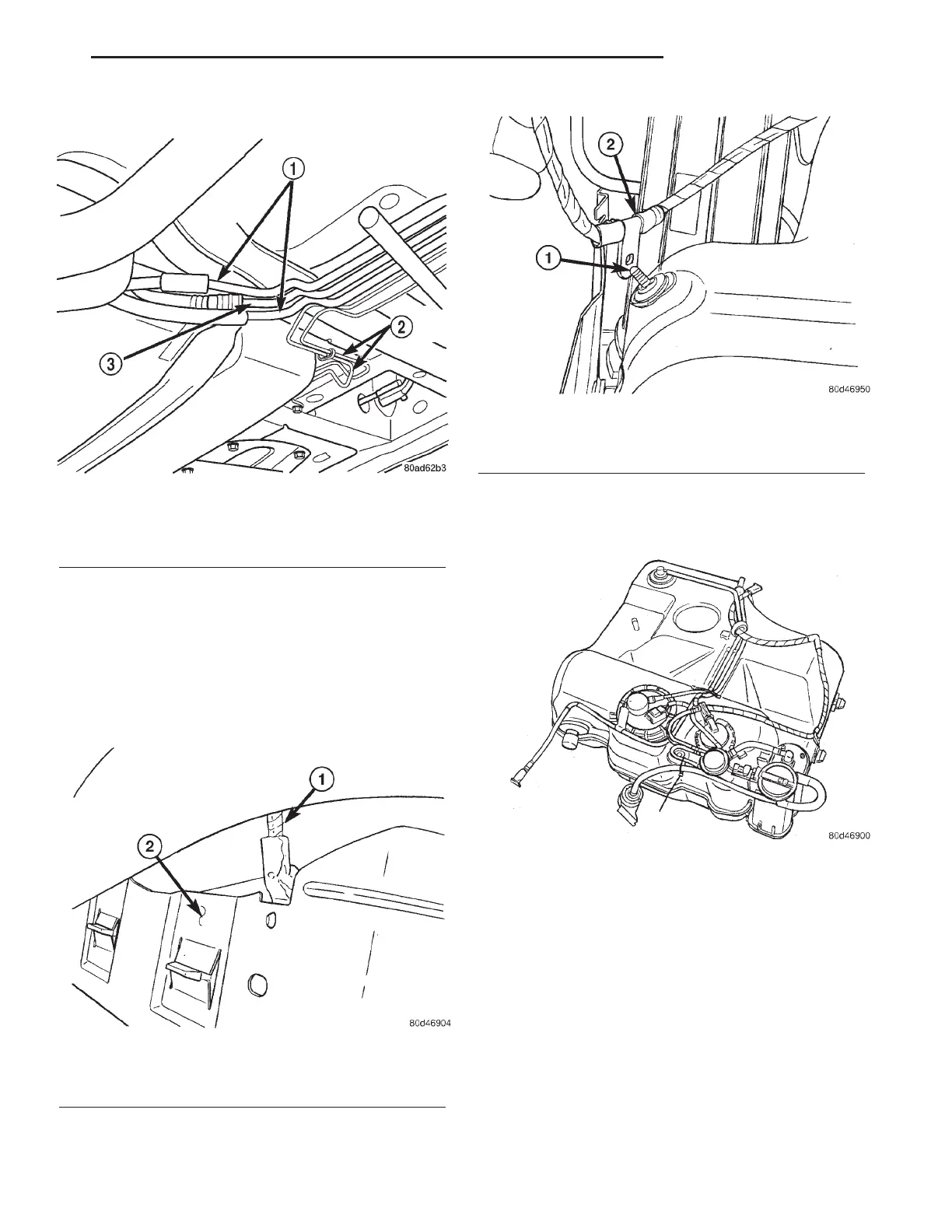
(8) Disconnect fuel and EVAP lines (Fig. 21).
(9) Position transmission jack under fuel tank
assembly.
(10) Remove fuel tank straps bolts. Passenger side
first.
(11) Lower fuel tank and remove the purge line
and vent line.
(12) Remove the wiring harness from the heat
shield, if needed (Fig. 22).
(13) Lower tank more and remove the wiring har-
ness from fuel tank pin, if needed (Fig. 23).
(14) Remove wiring harness from body.
(15) Remove NVLD filter from mounting location.
(16) Remove fuel tank (Fig. 24).
INSTALLATION
(1) Raise the fuel tank on the transmission stand
(Fig. 24).
(2) Install fuel pump electrical connector into hole
in the body.
(3) Connect wiring harness to fuel tank pin, if
removed (Fig. 23).
(4) Connect wiring harness to heat shield, if
removed (Fig. 22).
(5) Connect the purge and vent lines (Fig. 21).
(6) Raise tank into position and install tank
straps.
(7) Install the fuel filler tube and tighten the
clamp (Fig. 18).
(8) Reposition the stabilizer bar and install bolts.
Fig. 21 Fuel and EVAP Lines
1 - EVAP LINES
2 - BRAKE LINES
3 - FUEL LINE
Fig. 22 HARNESS TAB ON HEAT SHIELD
1 - Wiring Harness
2 - Heat Shield
Fig. 23 HARNESS ON TANK PIN
1 - Pin
2 - Wiring Harness
Fig. 24 FUEL TANK
LH FUEL DELIVERY 14 - 13
FUEL TANK (Continued)