NOTE: Multi-Layer Steel (MLS) head gaskets require
a scratch free sealing surface.
Remove all gasket material from cylinder head and
block (Refer to 9 - ENGINE - STANDARD PROCE-
DURE). Be careful not to gouge or scratch the alumi-
num head sealing surface.
Clean all engine oil passages.
INSPECTION
(1) Before cleaning, check for leaks, damage and
cracks.
(2) Clean cylinder head and oil passages.
(3) Check cylinder head for flatness (Fig. 12).
(4) Cylinder head must be flat within:
• Standard dimension = less than 0.05 mm (0.002
inch.)
• Service Limit = 0.2 mm (0.008 inch.)
• Grinding Limit = Maximum of 0.2 mm (0.008
inch.) is permitted.
CAUTION: 0.20 mm (0.008 in.) MAX is a combined
total dimension of the stock removal limit from cyl-
inder head and block top surface (Deck) together.
INSTALLATION
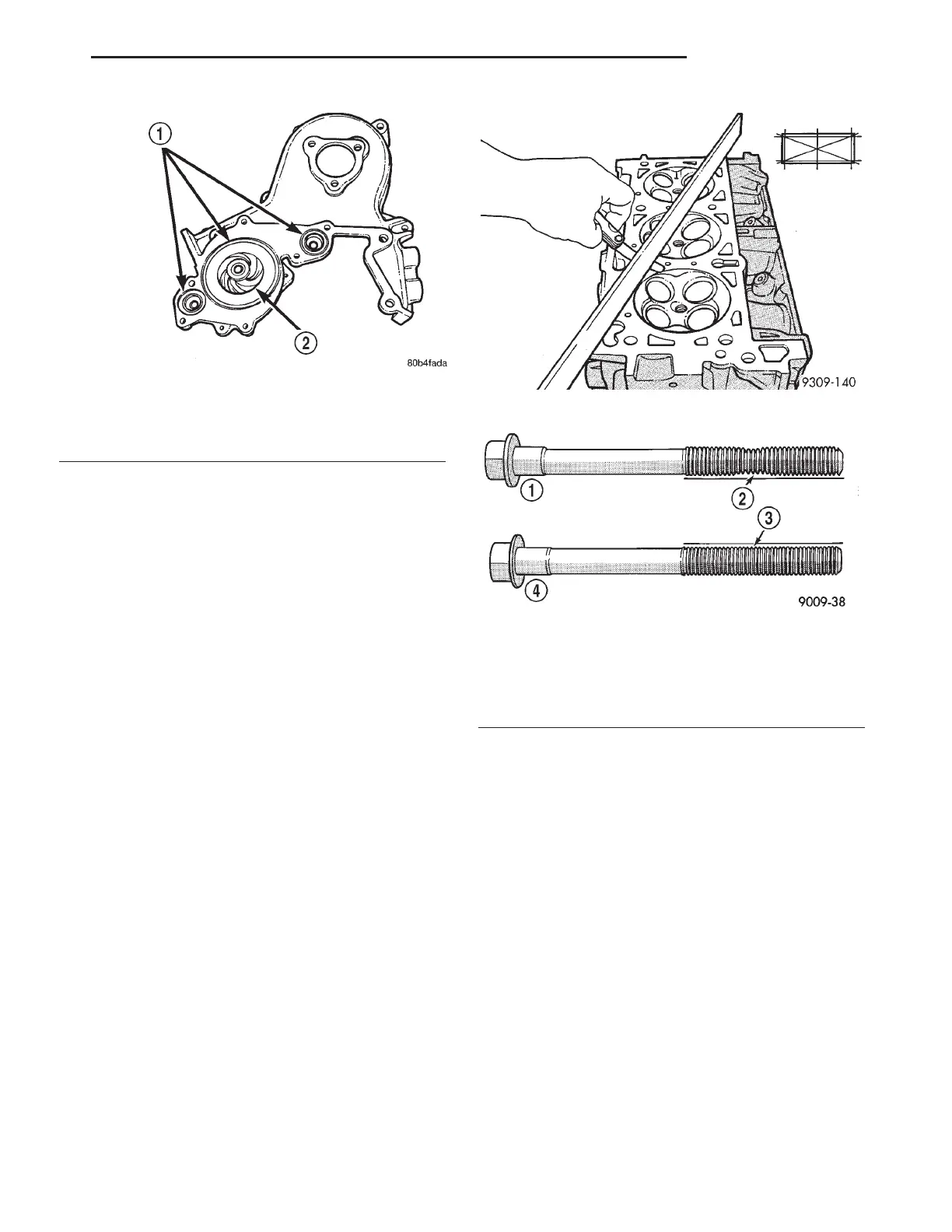
The cylinder head bolts are tightened using a
torque plus angle procedure. The bolts must be
examined BEFORE reuse. If the threads are
necked down the bolts must be replaced (Fig.
13).
Necking can be checked by holding a scale or
straight edge against the threads. If all the threads
do not contact the scale the bolt must be replaced.
CAUTION: When cleaning cylinder head and cylin-
der block surfaces, DO NOT use a metal scraper
because the surfaces could be cut or ground. Use
ONLY a wooden or plastic scraper.
(1) Clean sealing surfaces of cylinder head and
block.
CAUTION: Ensure that the correct head gaskets are
used and are oriented correctly on cylinder block.
The 3.5L engine head gaskets have perfectly round
combustion sealing rings. The 3.2L engine does
NOT have perfectly round combustion sealing
rings.
(2) Install head gasket over locating dowels.
Ensure the gasket is installed on the correct side of
engine (Fig. 14).
(3) Install cylinder head over locating dowels.
(4) Before installing the bolts, lubricate the
threads with engine oil.
(5) Tighten the cylinder head bolts in the sequence
shown in (Fig. 15). Using the 4 step torque-turn
Fig. 11 Right Side Timing Belt Cover Water Pump
O-Rings
1 - O-RINGS
2 - WATER PUMP IMPELLER
Fig. 12 Checking Cylinder Head Flatness
Fig. 13 Checking Bolts for Stretching (Necking)
1 - STRETCHED BOLT
2 - THREADS ARE NOT STRAIGHT ON LINE
3 - THREADS ARE STRAIGHT ON LINE
4 - UNSTRETCHED BOLT
LH ENGINE 3.5L 9 - 111
CYLINDER HEAD (Continued)