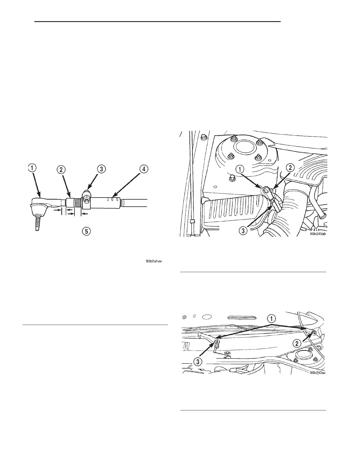
CAUTION: When setting the front Toe on the vehi-
cle, the maximum dimension of exposed threads
allowed on the adjuster and outer tie rod cannot
exceed the distance shown in (Fig. 49). If the maxi-
mum distance is exceeded, inadequate retention of
either the adjuster or the outer tie rod can result.
This condition can cause separation of the outer tie
rod end from the inner tie rod. Ensure that adjust-
ment sleeve pinch bolts are torqued to the required
specification when Toe setting procedure is com-
pleted.
(6) Check the front wheel toe setting on vehicle
and make required changes. When making front
wheel toe adjustments, be sure the maximum
exposed thread requirements (Fig. 49) are not
exceeded.
CAUTION: When torquing the adjuster pinch bolt,
the following procedure must be followed to ensure
adequate retention of the adjuster is obtained. Not
following this procedure, could result in the Toe
Setting Adjustment changing and/or the separation
of the outer tie rod from the inner tie rod.
(7) After completion of the tie rod end installation
and the toe adjustment procedure, tighten adjuster
pinch bolt (Fig. 49) to a torque of 38 N·m (28 ft. lbs.).
Make sure the outer tie rod maintains correct per-
pendicular orientation while tightening the adjuster
pinch bolt.
BUSHING - INNER TIE ROD
REMOVAL - INNER TIE ROD BUSHING
NOTE: When servicing inner tie rod bushings,
replacement of both inner tie rod bushings is rec-
ommended.
(1) Remove the battery ground cable from the
ground stud on the shock tower and isolate the
ground cable by installing the cable isolator on the
ground stud (Fig. 50).
(2) Remove caps from both wiper arms at the
attachment to the pivots to expose the wiper arm
attaching nut. Remove the nut attaching each wiper
arm to its pivot (Fig. 51).
Fig. 49 Tie Rod Thread Engagement Requirements
1 - OUTER TIE ROD
2 - ADJUSTER
3 - PINCH BOLT
4 - INNER TIE ROD
5 - ALLOWABLE THREADS EXPOSED ON OUTER TIE ROD AND
ADJUSTER IS A MAXIMUM OF 20 MILLIMETERS. REFER TO
AREA INDICATED ABOVE ON THE OUTER TIE ROD AND
ADJUSTER.
Fig. 50 Correctly Isolated Remote Ground Cable
1 - CABLE ISOLATOR
2 - GROUND STUD
3 - GROUND CABLE
Fig. 51 Wiper Arm Attachment To Pivot
1 - WIPER ARMS
2 - ATTACHING NUT
3 - ATTACHING NUT
LH GEAR 19 - 47
TIE ROD - OUTER (Continued)