FUEL INJECTOR
DESCRIPTION
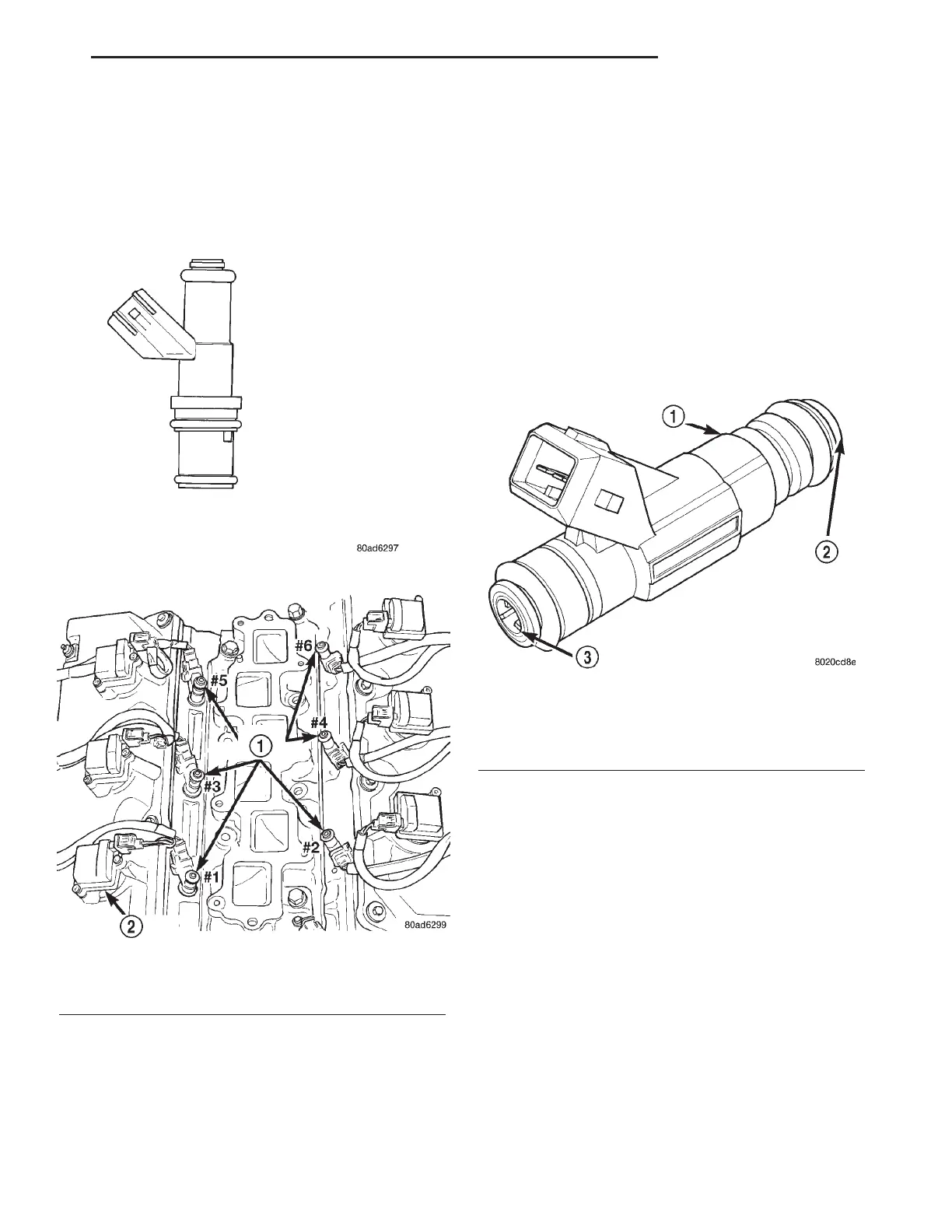
The injectors are positioned in the cylinder heads
with the nozzle ends directly above the intake valve
port (Fig. 8). The fuel injectors are electrical sole-
noids (Fig. 7).
OPERATION
The fuel injectors are 12 volt electrical solenoids
(Fig. 9). The injector contains a pintle that closes off
an orifice at the nozzle end. When electric current is
supplied to the injector, the armature and needle
move a short distance against a spring, allowing fuel
to flow out the orifice. Because the fuel is under high
pressure, a fine spray is developed in the shape of a
hollow cone or two streams. The spraying action
atomizes the fuel, adding it to the air entering the
combustion chamber. Fuel injectors are not inter-
changeable between engines.
The PCM provides battery voltage to each injector
through the ASD relay. Injector operation is con-
trolled by a ground path provided for each injector by
the PCM. Injector on-time (pulse-width) is variable,
and is determined by the PCM processing all the
data previously discussed to obtain the optimum
injector pulse width for each operating condition. The
pulse width is controlled by the duration of the
ground path provided.
REMOVAL
REMOVAL - 2.7L
(1) Release fuel system pressure. Refer to Fuel
System Pressure Release Procedure in this section.
(2) Disconnect negative cable to battery.
(3) Remove intake manifold plenum. Refer to the
Engine section for information.
(4) Remove intake manifold plenum mounting
bolts. Lift Plenum up off of engine. Cover intake
manifold to prevent foreign material from entering
engine.
(5) Disconnect fuel supply tube quick connect fit-
tings at the rear of intake manifold. Refer to Quick
Connect Fittings in the Fuel Delivery Section.
(6) If the injector connectors are not tagged with
their cylinder number, tag them to identify the cor-
rect cylinder
Fig. 7 Fuel Injector - Typical
Fig. 8 Fuel Injector Location—Typical
1 - FUEL INJECTORS
2 - IGNITION COILS
Fig. 9 FUEL INJECTOR - TYPICAL
1 - FUEL INJECTOR
2 - NOZZLE
3 - TOP (FUEL ENTRY)
LH FUEL INJECTION 14 - 27