VALVE SPRINGS
DESCRIPTION
The valve springs are made from chrome silicon
alloy wire and incorporate a “bee-hive” design. Valve
spring retainers and locks are common from valve-to-
valve. The valve spring seat is integral with the
valve stem oil seal, which incorporates a garter
spring to maintain consistent lubrication control to
the valve stem.
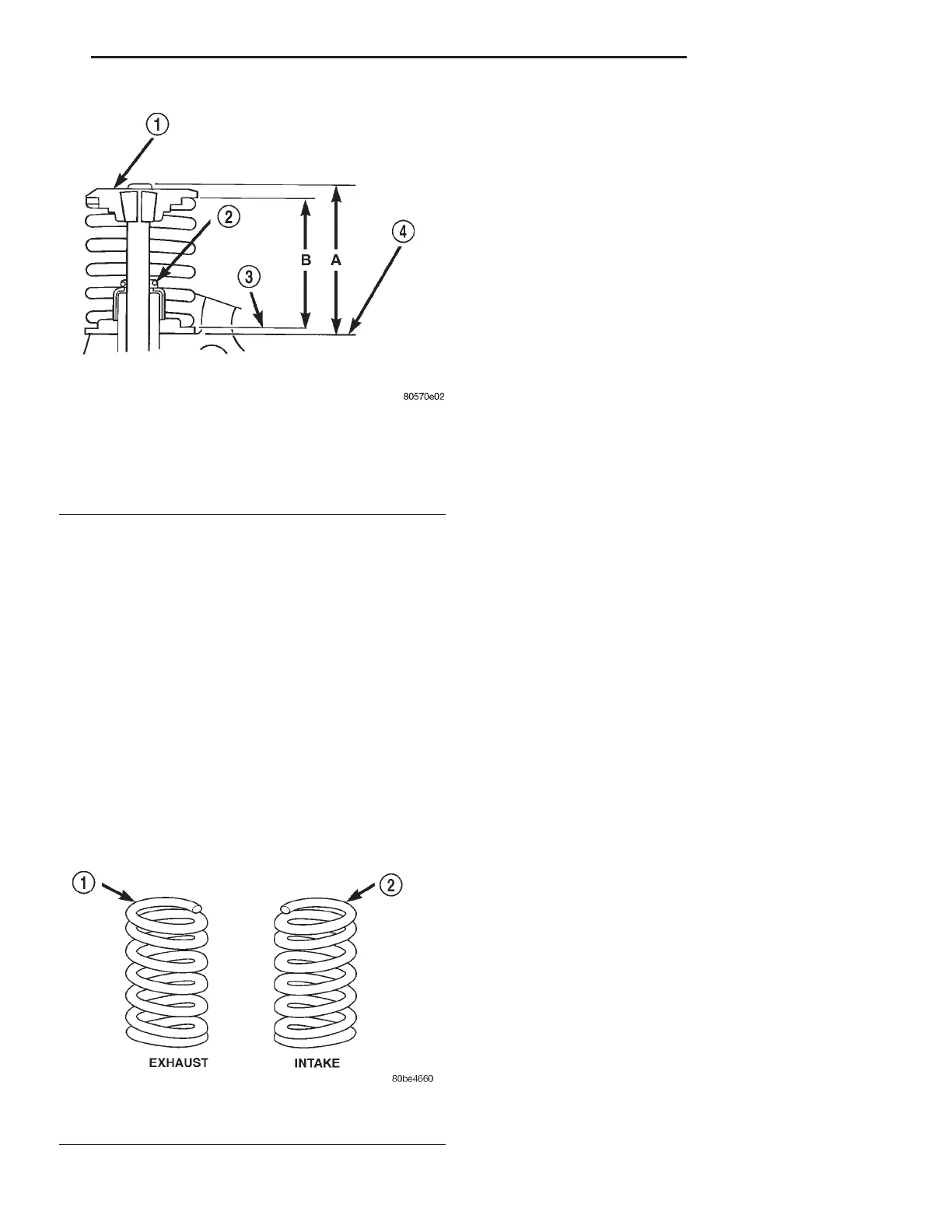
The valve springs are unique for intake compared
to exhaust. Both have different lengths and are
wound in opposite directions. The valve springs are
color coded, intake spring is right hand coil direction
with orange dye on the top coils, and the exhaust
spring is left hand coil direction with a yellow dye on
the top coils (Fig. 49).
OPERATION
The valve spring returns the valve against its seat
for a positive seal of the combustion chamber.
REMOVAL
REMOVAL - CYLINDER HEAD OFF
(1) Using Special Tool C-3422–D (valve spring
compressor) with Adapter 6526 compress valve
spring and remove valve retaining locks. For Special
Tool identification, (Refer to 9 - ENGINE - SPECIAL
TOOLS).
(2) Slowly release valve spring compressor.Remove
valve spring retainer and valve spring.
(3) Remove valve stem seal assembly (Refer to 9 -
ENGINE/CYLINDER HEAD/VALVE STEM SEALS -
REMOVAL).
REMOVAL - CYLINDER HEAD ON
(1) Perform fuel system pressure release procedure
before attempting any repairs. (Refer to 14 -
FUEL SYSTEM/FUEL DELIVERY - STANDARD
PROCEDURE)
(2) Disconnect negative cable from battery.
(3) Remove air cleaner housing and hose assembly.
(4) Remove upper intake manifold. (Refer to 9 -
ENGINE/MANIFOLDS/INTAKE MANIFOLD -
REMOVAL)
(5) Remove cylinder head covers. (Refer to 9 -
ENGINE/CYLINDER HEAD/CYLINDER HEAD
COVER(S) - REMOVAL)
(6) Remove rocker arm and shaft assembly. (Refer
to 9 - ENGINE/CYLINDER HEAD/ROCKER ARM /
ADJUSTER ASSY - REMOVAL)
(7) Remove spark plugs. (Refer to 8 - ELECTRI-
CAL/IGNITION CONTROL/SPARK PLUG -
REMOVAL)
(8) Rotate the crankshaft clockwise, until the num-
ber 1 piston is at TDC (Top Dead Center) on the com-
pression stroke.
(9) With air hose attached to spark plug adapter
installed in number 1 spark plug hole, apply 620.5 to
689 kPa (90 to 100 psi) air pressure. This is to hold
valves into place while servicing components.
(10) Using Tool MD 998772A with adapter 6527 or
equivalent, compress valve spring and remove valve
locks, retainer, and valve spring.
(11) Remove valve stem seal, if required. (Refer to
9 - ENGINE/CYLINDER HEAD/VALVE STEM
SEALS - REMOVAL)
(12) Follow the same procedure on the remaining 5
cylinders using the firing sequence 1-2-3-4-5-6. Make
sure piston is at TDC in each cylinder of the
valve spring that is being removed.
(13) Remove spark plug adapter tool.
Fig. 48 Checking Valve Tip Height and Valve Spring
Installed Height
1 - SPRING RETAINER
2 - GARTER SPRING
3 - VALVE SPRING SEAT TOP
4 - CYLINDER HEAD SURFACE
Fig. 49 Valve Spring Identification
1 - YELLOW DYE
2 - ORANGE DYE
LH ENGINE 3.5L 9 - 125
VALVE STEM SEALS (Continued)