CONNECTING ROD BEARINGS
STANDARD PROCEDURE - CONNECTING RODS
AND BEARINGS
CONNECTING ROD BEARINGS
The bearing caps are not interchangeable and
should be marked at removal to insure correct
assembly.
The bearing shells must be installed with the
tangs inserted into the machined grooves in the rods
and caps. Install cap with the tangs on the same side
as the rod.
Fit all rods on one bank until complete.
Limits of taper or out-of-round on any crankshaft
journals should be held to 0.015 mm (0.0006 in.).
Bearings are available in standard, 0.025 mm (0.001
in.), and 0.254 mm (0.010 in.) undersizes. Install the
bearings in pairs. Do not use a new bearing
half with an old bearing half. Do not file the
rods or bearing caps.
(1) For measuring main bearing clearance and con-
necting rod bearing clearance use plastigage (Fig.
56). For more information on using plastigage (Refer
to 9 - ENGINE - STANDARD PROCEDURE). Refer
to Engine Specifications for bearing clearance specifi-
cations (Refer to 9 - ENGINE - SPECIFICATIONS).
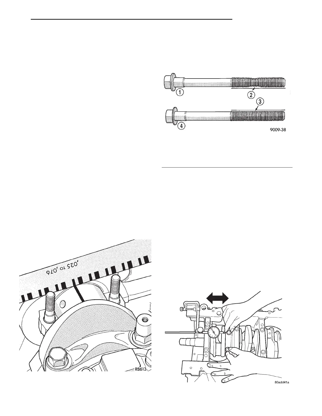
NOTE: The rod bearing bolts should be examined
before reuse. If the threads are necked down the
bolts must be replaced (Fig. 57).
CONNECTING ROD BOLTS
(1) Examine connecting rod bolts for stretching.
Stretching can be checked by holding a scale or
straight edge against the threads. If all the threads
do not contact the scale the bolt must be replaced.
(2) Before installing the nuts the threads should
be oiled with engine oil.
(3)
Install nuts on each bolt finger tight. Then alter-
nately torque each nut to assemble the cap properly.
(4) Tighten the connecting rod cap nuts to specifi-
cations. (Refer to 9 - ENGINE - SPECIFICATIONS)
CONNECTING ROD SIDE CLEARANCE
(1) Mount a dial indicator to a stationary point on
engine. Locate probe perpendicular to and resting
against the connecting rod cap being checked. Move
connecting rod all the way to rear of its travel. Zero
the dial indicator. Move connecting rod forward to
limit of travel and read the dial indicator (Fig. 58).
Compare measurement to specification listed in
engine specifications (Refer to 9 - ENGINE - SPECI-
FICATIONS). Repeat procedure for each connecting
rod. Turn crankshaft for connecting rod accessibility.
Fig. 56 CHECKING CONNECTING ROD BEARING
Fig. 57 CHECK FOR STRETCHED BOLTS
1 - STRETCHED BOLT
2 - THREADS ARE NOT STRAIGHT ON LINE
3 - THREADS ARE STRAIGHT ON LINE
4 - UNSTRETCHED BOLT
Fig. 58 CONNECTING ROD SIDE CLEARANCE
LH ENGINE 3.5L 9 - 129