CONNECTING ROD SIDE CLEARANCE
(1) Mount a dial indicator to a stationary point on
engine. Locate probe perpendicular to and resting
against the connecting rod cap being checked. Move
connecting rod all the way to rear of its travel. Zero
the dial indicator. Move connecting rod forward to
limit of travel and read the dial indicator (Fig. 47).
Compare measurement to specification listed in
engine specifications (Refer to 9 - ENGINE - SPECI-
FICATIONS). Repeat procedure for each connecting
rod. Turn crankshaft for connecting rod accessibility.
CRANKSHAFT
DESCRIPTION
The crankshaft is constructed of a forged micro
alloy steel. The six throw, nine counterweight crank-
shaft is supported by four select fit main bearings
with the number three serving as the thrust washer
location (Fig. 42). The select fit identification mark-
ings will be on the rear side of the number nine
(rearmost) counterweight. The six separate connect-
ing rod throws are an even-firing design which
reduces torque fluctuations while a vibration damper
is used to control torsional vibration.
The crankshaft oil seals are a one piece design.
The front seal is retained by the timing chain cover,
and the rear seal in a housing that attaches to the
cylinder block.
OPERATION
The crankshaft transfers force generated by com-
bustion within the cylinder to the flywheel or flex-
plate.
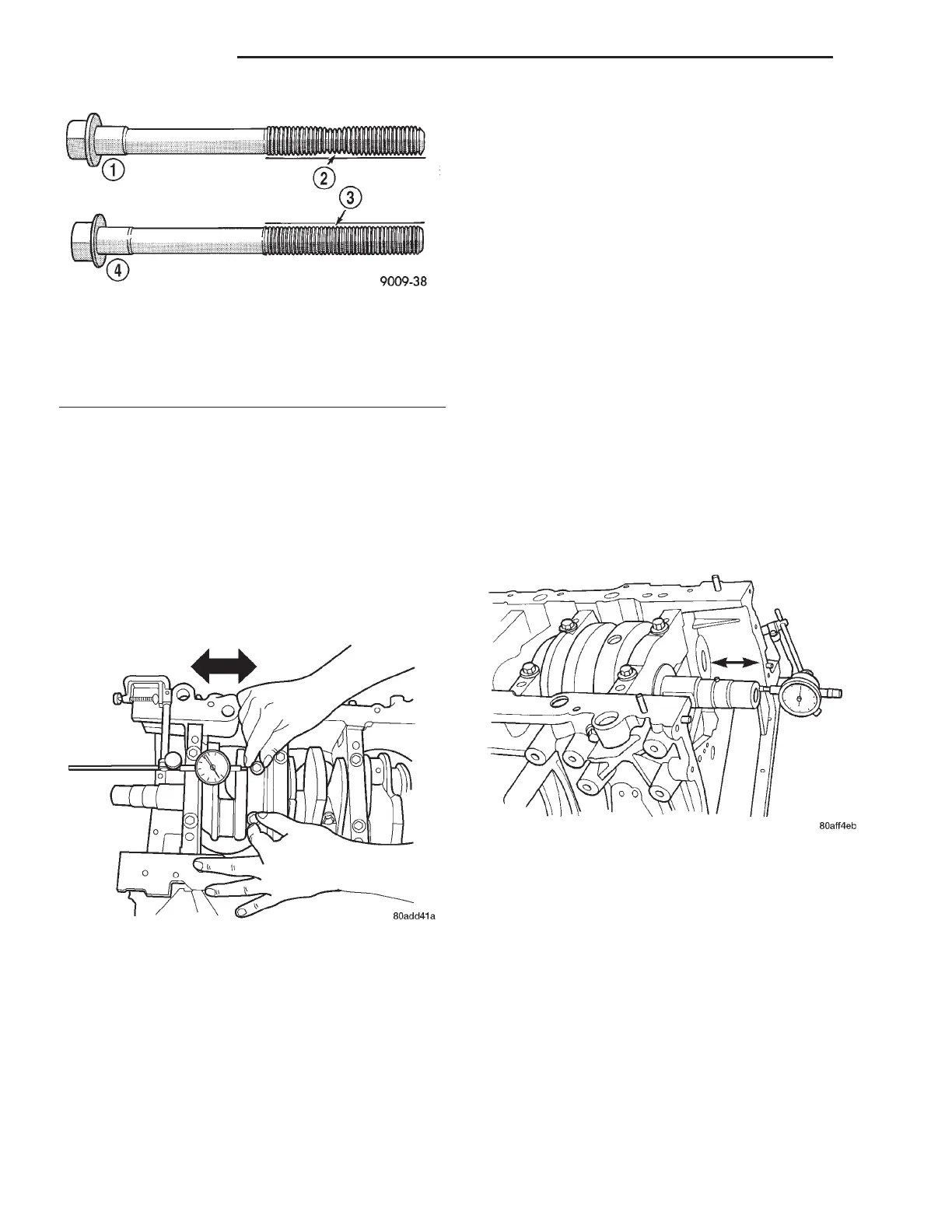
STANDARD PROCEDURE - CRANKSHAFT END
PLAY
(1) Mount a dial indicator to a stationary point at
front of engine. Locate the probe perpendicular
against nose of crankshaft (Fig. 48).
(2) Move crankshaft all the way to the rear of its
travel.
(3) Zero the dial indicator.
(4) Move crankshaft all the way to the front and
read the dial indicator. For crankshaft end play clear-
ances (Refer to 9 - ENGINE - SPECIFICATIONS).
REMOVAL
(1) Remove engine from vehicle (Refer to 9 -
ENGINE - REMOVAL).
(2) Mount engine on an engine stand.
(3) Drain engine oil and remove oil filter.
(4) Remove oil pan and oil pick-up tube (Refer to 9
- ENGINE/LUBRICATION/OIL PAN - REMOVAL).
(5) Remove idler pulley bracket for accessory drive
belt.
(6) Remove upper intake manifold (Refer to 9 -
ENGINE/MANIFOLDS/INTAKE MANIFOLD -
REMOVAL).
(7) Remove cylinder head covers (Refer to 9 -
ENGINE/CYLINDER HEAD/CYLINDER HEAD
COVER(S) - REMOVAL).
Fig. 46 Check for Stretched Bolts
1 - STRETCHED BOLT
2 - THREADS ARE NOT STRAIGHT ON LINE
3 - THREADS ARE STRAIGHT ON LINE
4 - UNSTRETCHED BOLT
Fig. 47 Connecting Rod Side Clearance Measuring
Fig. 48 CHECKING CRANKSHAFT END PLAY
9 - 42 ENGINE 2.7L LH
CONNECTING ROD BEARINGS (Continued)