(5) Position wire harness on cylinder head cover
and install retaining nuts (Fig. 22).
(6) Install ignition coils and connect all electrical
connectors (Fig. 23).
(7) Install upper intake manifold. (Refer to 9 -
ENGINE/MANIFOLDS/INTAKE MANIFOLD -
INSTALLATION)
(8) Install air cleaner assembly.
INTAKE/EXHAUST VALVES &
SEATS
DESCRIPTION
Valves are made of highly heat-resistant steel and
are chrome plated to prevent stem scuffing. The
intake valve is a one-piece forging, while the exhaust
valve has a forged head with a welded stem for lock
groove hardenability. The four valves (two intake and
two exhaust) employ a three-groove lock design to
help facilitate valve rotation.
OPERATION
The intake valve allows the air/fuel mixture to
enter the combustion chamber. The exhaust valve
allows the burned air/fuel mixture to exit the com-
bustion chamber. Also, the intake and exhaust valves
seal the combustion chamber during the compression
and power strokes.
STANDARD PROCEDURE - VALVE AND VALVE
SEAT REFACING
The valve face and valve seat angles are shown in
(Fig. 28).
VALVES
(1) Inspect the remaining margin after the valves
are refaced (Fig. 27). (Refer to 9 - ENGINE - SPEC-
IFICATIONS)
VALVE SEATS
(1) When refacing valve seats, it is important that
the correct size valve guide pilot be used for reseat-
ing stones. A true and complete surface must be
obtained.
(2) Measure the concentricity of valve seat using
dial indicator. Total runout should not exceed 0.051
mm (0.002 inch.) total indicator reading.
(3) Inspect the valve seat with Prussian blue to
determine where the valve contacts the seat. To do
this, coat valve seat LIGHTLY with Prussian blue
then set valve in place. Rotate the valve with light
pressure. If the blue is transferred to the center of
valve face, contact is satisfactory. If the blue is trans-
ferred to top edge of valve face, then lower valve seat
with a 15 degree stone. If the blue is transferred to
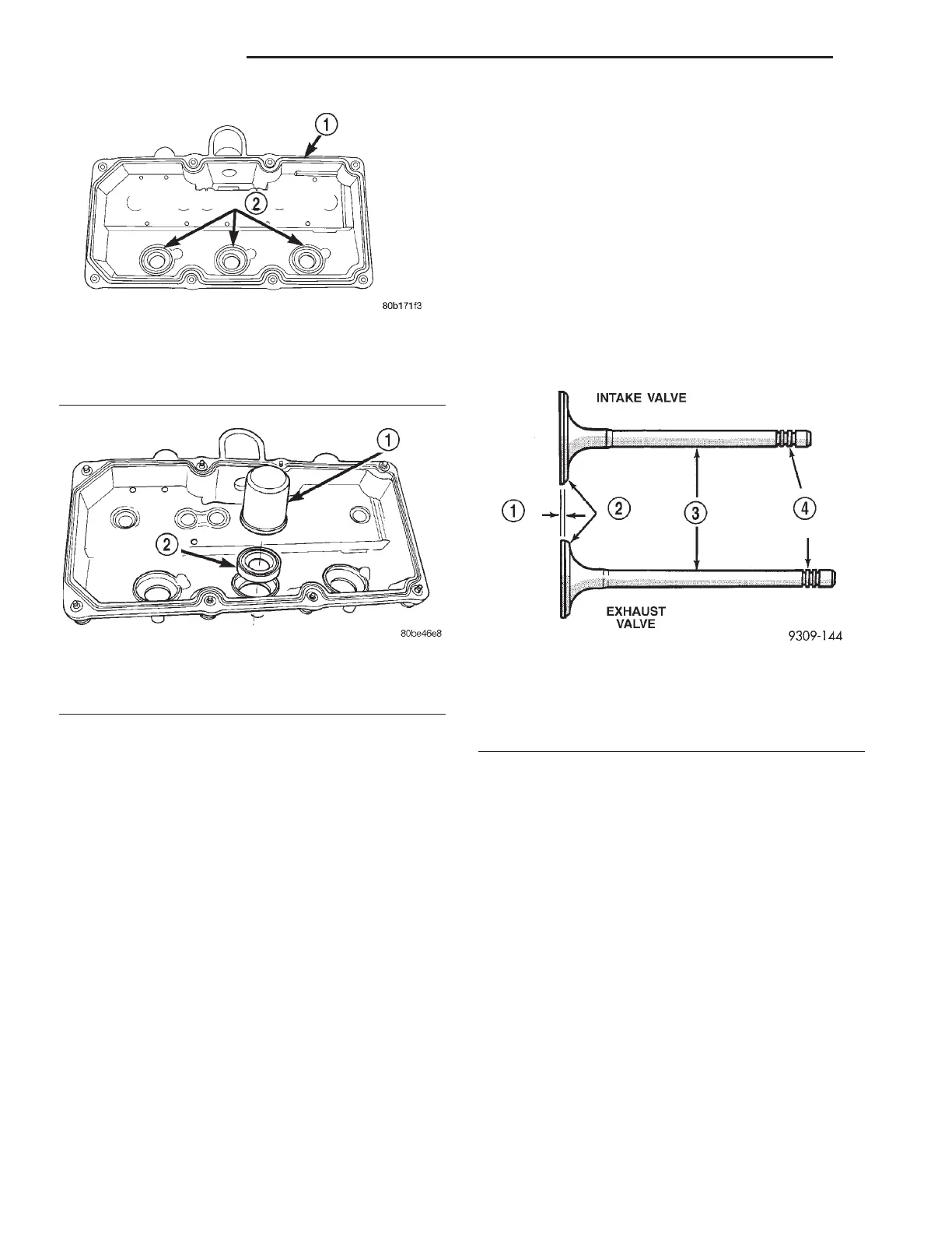
Fig. 25 Cylinder Head Cover Gasket and Spark Plug
Tube Seals
1 - CYLINDER HEAD COVER GASKET
2 - SPARK PLUG TUBE SEALS
Fig. 26 Spark Plug Tube Seal Installation
1 - SPECIAL TOOL MD-998306
2 - SPARK PLUG TUBE SEAL
Fig. 27 Intake and Exhaust Valves
1 - MARGIN
2-FACE
3 - STEM
4 - VALVE SPRING RETAINER LOCK GROOVES
9 - 116 ENGINE 3.5L LH
CYLINDER HEAD COVER(S) (Continued)