CAUTION: Oil pump pressure relief valve must be
installed as shown in (Fig. 96) or engine damage
may occur.
(2) Remove spring and relief valve.
(3) Remove oil pump cover screws and lift off cover
plate (Fig. 97).
(4) Remove pump rotors.
(5) Wash all parts in a suitable solvent.
(6) Inspect components carefully for damage or
wear. (Refer to 9 - ENGINE/LUBRICATION/OIL
PUMP - INSPECTION)
CLEANING
(1) Clean all parts thoroughly in a suitable sol-
vent.
INSPECTION
(1) Disassemble the oil pump. (Refer to 9 -
ENGINE/LUBRICATION/OIL PUMP - DISASSEM-
BLY)
(2) Clean all oil pump components. (Refer to 9 -
ENGINE/LUBRICATION/OIL PUMP - CLEANING)
(3) Inspect mating surface of the oil pump housing
and cover. Replace oil pump if deeply scratched or
grooved (minor surface scratches and polishing is
normal).
(4) Lay a straightedge across the pump cover sur-
face (Fig. 98). If a 0.025 mm (0.001 in.) feeler gauge
can be inserted between cover and straight edge,
cover should be replaced.
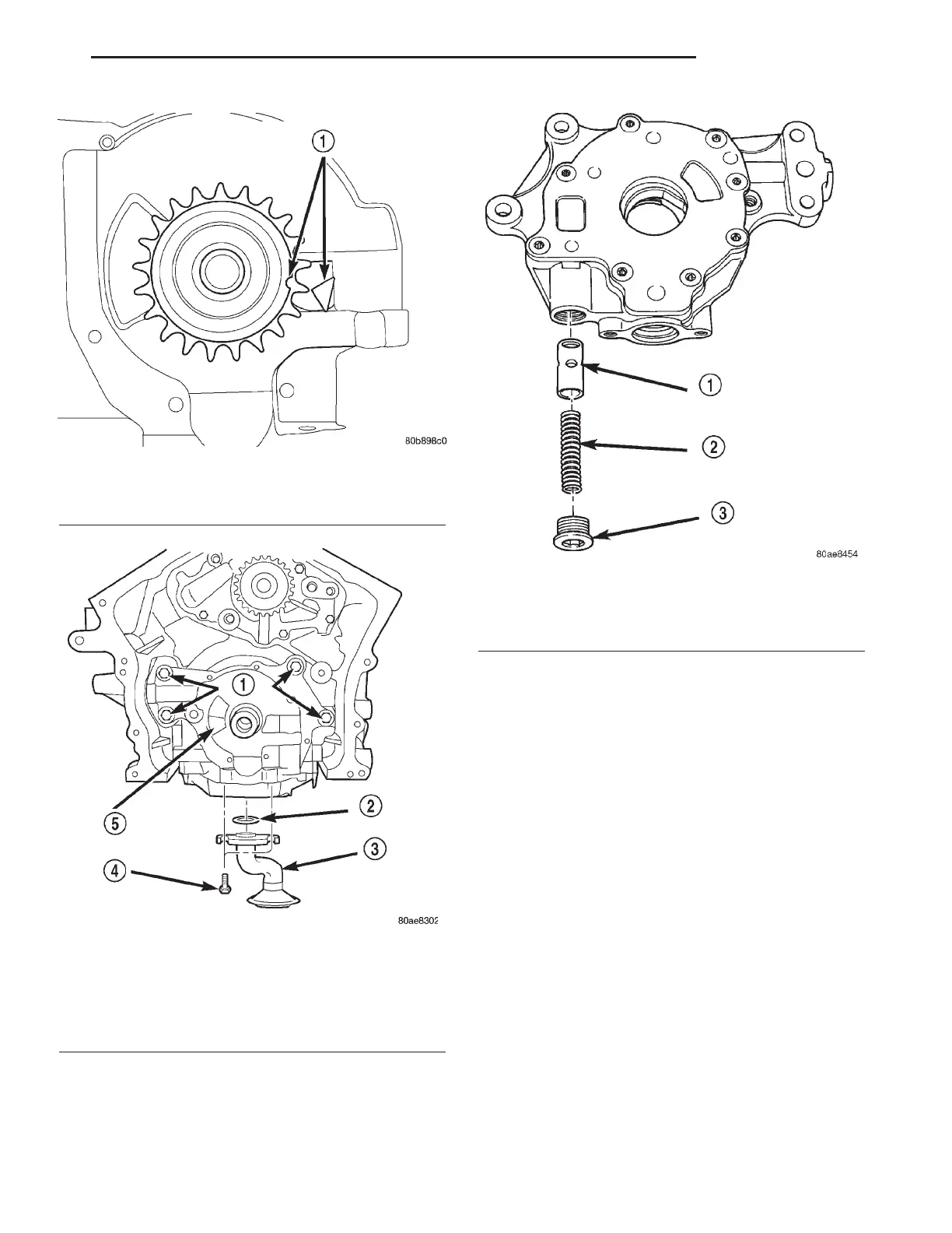
Fig. 94 Crankshaft Positioned At 60 DEGREES
ATDC No.1 Cylinder
1 - CRANKSHAFT POSITION = 60° ATDC NO. 1 CYLINDER
Fig. 95 Oil Pump and Pick-up Tube
1 - BOLTS
2 - O-RING
3 - PICK-UP TUBE
4 - BOLT
5 - OIL PUMP
Fig. 96 Oil Pressure Relief Valve
1 - RELIEF VALVE
2 - SPRING
3 - RETAINER CAP
LH ENGINE 2.7L 9 - 69
OIL PUMP (Continued)