(9) Install the ignition switch on the steering col-
umn. Install and securely tighten the 2 screws (Fig.
19) mounting the ignition switch to the steering col-
umn.
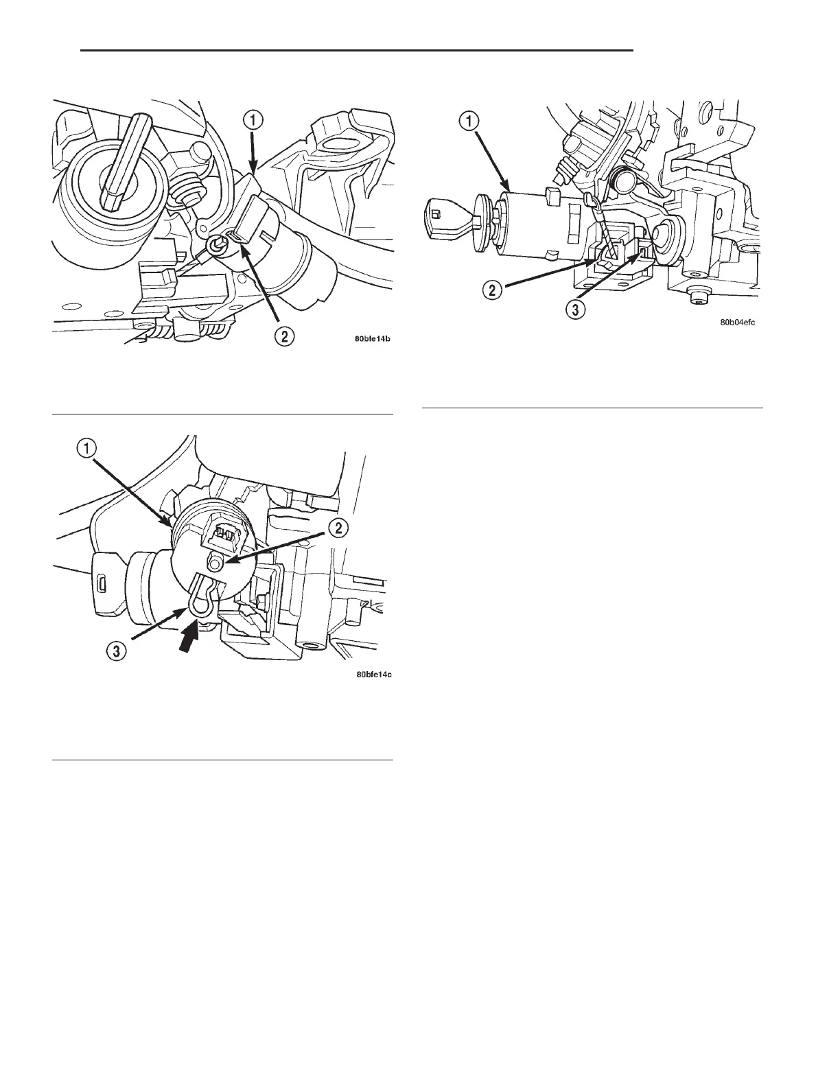
(10) If the vehicle is equipped with a steering col-
umn mounted shift lever and if a new ignition shift
interlock cassette has been installed, the interlock
system must be adjusted. Adjust the interlock system
by pushing in on the adjustment tab until it stops
(Fig. 32). The adjustment tab will click as it moves
into position. Ensure the tab is fully depressed.
(11) Install the multi-function switch on the steer-
ing column. Install and securely tighten the two
screws (Fig. 18) mounting the multi-function switch
to the steering column. Install the clockspring wiring
harness on the routing clip on the top of the multi-
function switch.
(12) Clip the SKIM module over the key cylinder
halo bezel and attach it to the steering column with
its mounting screw. Connect the wiring harness to
the module.
(13) Install the clockspring on the steering column.
Install and securely tighten the two screws (Fig. 17)
mounting the clockspring to the steering column.
(14) Install the wiring harness connectors (Fig. 16)
on the clockspring.
(15) If removed, install the trim ring for the key
cylinder on the lock cylinder housing.
(16) Install the lower shroud (Fig. 15) on the steer-
ing column. Install and securely tighten the 2 screws
attaching the lower shroud to the steering column.
(17) Install the tilt lever (Fig. 14) on the steering
column.
(18) Install the upper shroud on the steering col-
umn by snapping it onto the lower shroud.
CAUTION: If any doubt is present as to whether the
clockspring is properly centered, This clockspring
centering procedure MUST be performed prior to
installing steering wheel assembly. If clockspring is
not centered it may be overextended, causing
clockspring assembly to become inoperative. The
yellow centering indicator must be present in the
centering window of the clockspring and the arrow
on the clockspring must be pointing at the drive
pin.
(19) Center the clock spring using the following
procedure.
• Depress the plastic locking pin to disengage
clockspring locking mechanism.
Fig. 30 Guide And Flange Alignment
1 - BRACKET FLANGE
2 - GUIDE
Fig. 31 Solenoid Retainer Clip Installation
1 - SOLENOID
2 - MOUNTING STUD
3 - RETAINER CLIP
Fig. 32 Ignition Interlock Adjustment Tab
1 - LOCK CYLINDER HOUSING
2 - INTERLOCK CASSETTE
3 - ADJUSTMENT TAB
LH COLUMN 19 - 21
COLUMN (Continued)