(34) Apply 30 psi (206 kPa) air pressure to the
reverse clutch hose on Tool 8391. Measure and record
reverse clutch pack measurement in four (4) places,
90° apart.
(35) Take average of four measurements and com-
pare with reverse clutch pack clearance specification.
The reverse clutch pack clearance is 0.89-1.37
mm (0.035-0.054 in.). Select the proper reverse
clutch snap ring to achieve specifications:
(36) To complete the assembly, reverse clutch and
overdrive clutch must be removed.
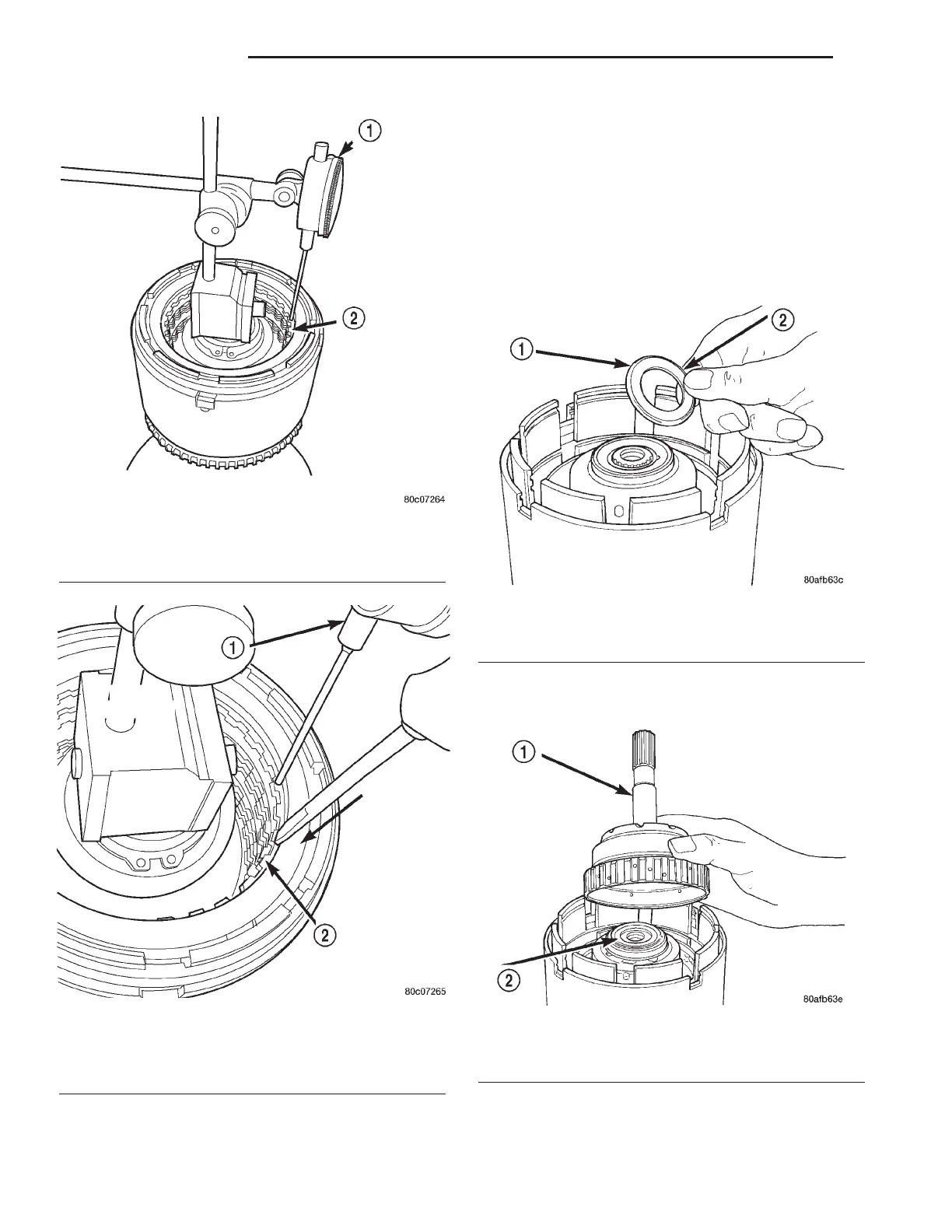
(37) Install the #2 needle bearing (Fig. 320).
(38) Install the underdrive shaft assembly (Fig.
321).
(39) Install the #3 thrust washer to the underdrive
shaft assembly. Be sure five tabs are seated properly
(Fig. 322).
Fig. 318 Measure Reverse Clutch Pack Clearance
1 - DIAL INDICATOR
2 - REVERSE CLUTCH
Fig. 319 Press Down on Reverse Clutch and Zero
Indicator
1 - DIAL INDICATOR
2 - REVERSE CLUTCH
Fig. 320 Install No. 2 Needle Bearing
1 - #2 NEEDLE BEARING (NOTE 3 SMALL TABS)
2 - TABS UP
Fig. 321 Install Underdrive Shaft Assembly
1 - UNDERDRIVE SHAFT ASSEMBLY
2 - #2 NEEDLE BEARING
21 - 122 TRANSAXLE LH
INPUT CLUTCH ASSEMBLY (Continued)
 Loading...


