2
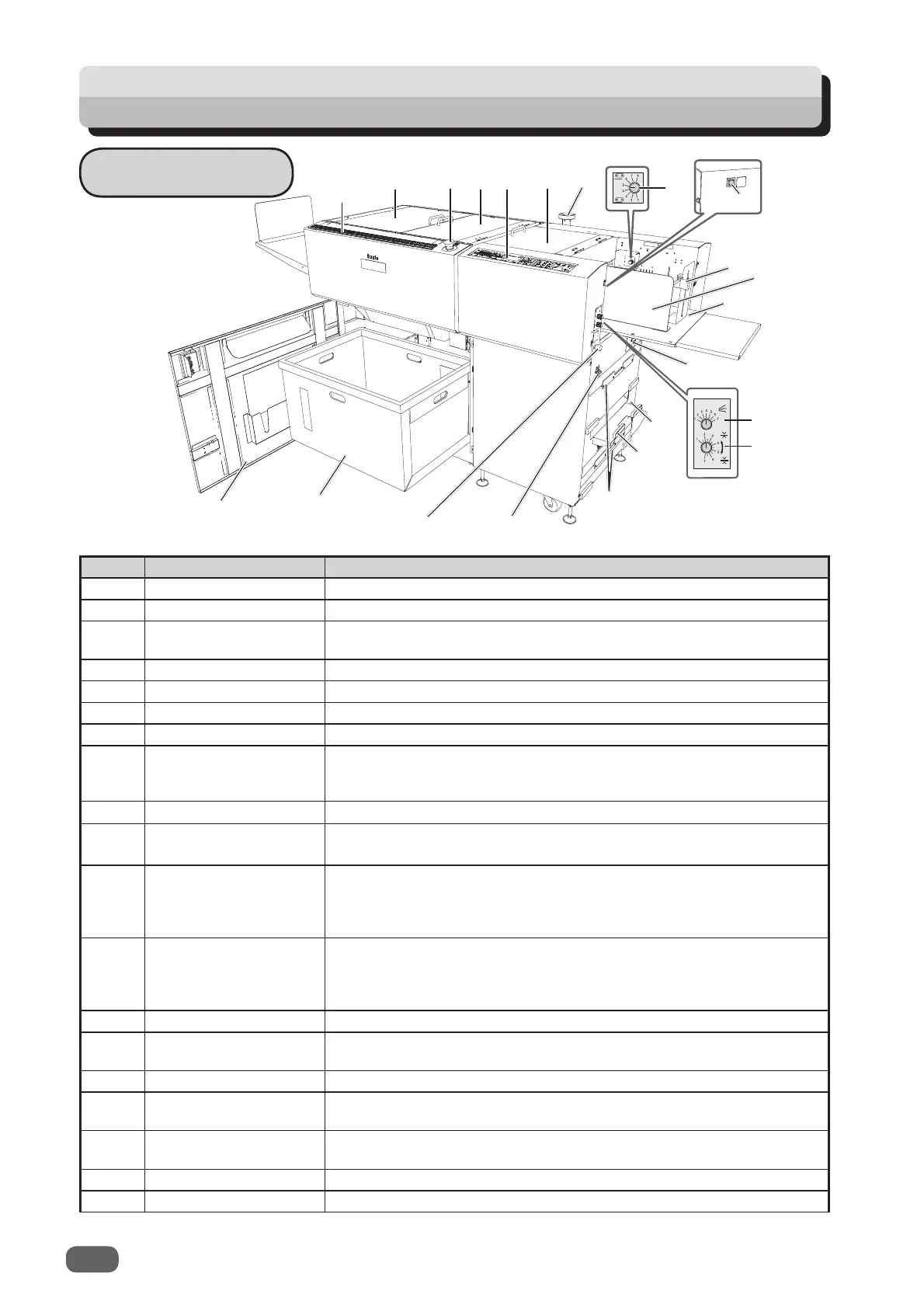
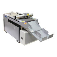
Part Names and Their Functions
Appearance
No.
Name
Function
1
Back guide
(for feed tray)
Set this according to the document size.
2
Side guide (for feed tray)
Set this according to the document size.
3
PC arm mount
Install a commercial monitor arm for putting the laptop computer.
(Model: 115V (USA), 230V (UK))
4 Feed tray Original document is placed here.
5 Level adjustment knob Adjusts the elevator height.
6
Airfl ow adjustment knob
Adjusts the airfl ow level.
7
Separator adjustment knob
Adjusts the distance between the separator and the conveyance belt.
8 Top cover 1 Open this to move the upper guide or to remove a document
jam from the document feed area. When the cover is
open, the
machine stops running
with the interlock switch.
9 Control panel Displays operations and status.
10
Emergency stop
switch
Press this to stop the machine in an emergency. Turning the
switch to the right releases the emergency stop.
11 Top cover 2
Open this to remove a document jam from the slitter/optional module
area
or to replace the optional module
.
When the cover is open, the machine stops running with the
interlock switch.
12 Top cover 3 Open this to remove a document jam from the cutter/crease/
optional module or to replace the optional module. When the
cover is
open, the machine stops running with the interlock
switch.
13 Scale Measures the cut and slit position, and the fi nished product.
14 Front cover Open this to remove the waste box. When the cover is
open, the
machine stops running
with the interlock switch.
15 Waste box Receives pieces of waste paper.
16 Reject tray This is where the document comes when it is rejected due to a
double feed, barcode error, REG mark error, etc.
17 USB terminal Used for the connection to your computer on the PC Controller
that you are using.
18 Skew adjustment knob Adjusts the document skew.
19 Power switch Move this up/down to turn the power ON/OFF.
2
1
3
4
5
6
7
8
9
10
11
13
12
14
15
17
18
19
16
21
22
20